 airbrakecompressor
To replace an air compressor discharge line, fit a high-temperature line of the original construction, length and inside diameter: wire-braided PTFE hose, copper or steel tube, or a combination of them. Route it on a continuous downhill slope from the compressor discharge port to the air dryer inlet, with gentle bends, no low spots and cushioned supports clear of exhaust heat. Nylon air brake tubing is never an acceptable substitute.
The discharge line is a heat exchanger and a drain, not just plumbing. Under sustained loaded running the discharge port can run well above 300°F, while desiccant air dryers are generally built for inlet air no hotter than roughly 160-175°F. As the air cools on the way down, its water and oil condense and run forward to the dryer, which expels them when it purges at governor cut-out. If the old line came off packed with coked oil, work through discharge line carbon buildup too; a new line on a compressor that passes oil will carbon up again.
Material: braided PTFE hose, copper or steel
Air dryer installation instructions call for wire-braided PTFE hose, copper tubing or a combination of both, and steel tube is also used. Detroit's engine literature, for example, specifies a rating of about 450°F for braided PTFE hose connected directly to the compressor. Reproduce the OE construction rather than improvising. The compressor moves with the engine on its mounts while the dryer is usually frame-mounted, so a rigid run needs a braided flexible section between them, or vibration cracks the tube at its fittings. When the original part number is known, pre-formed OE-grade compressor discharge pipes take the guesswork out of length, bends and end fittings.
Why nylon tubing must never be used
SAE J844 nylon air brake tubing is typically rated to roughly 200-250°F, and its pressure rating is quoted at room temperature. On a discharge line it fails three ways:
- It softens. Above its rating the tube loses burst strength, balloons, and can split or pull out of its fitting.
- It fails on the worst day. It can survive a cool, light shift, then let go on a long grade or behind a leak that keeps the compressor loaded.
- It sags and ages. Hot plastic droops into water-trapping low spots, and heat and oil vapor embrittle it.
Once it lets go, the compressor cannot charge the reservoirs. Brake applications pull pressure toward the low-air warning at around 60 psi, and the spring brakes apply if it falls into the 20-45 psi range. Push-to-connect fittings made for nylon tube are equally out of place; match the flare, compression or threaded fittings on the original line. General tubing and hose types are covered in air brake hoses and fittings.
Length and inside diameter
Length and bore set the air temperature at the dryer inlet: a longer or larger line cools the air more, but one that is too long condenses more water inside itself and freezes more readily. The vehicle manufacturer's specification comes first. Published compressor and dryer guidelines, which assume a normal duty cycle and a temperate climate, fall in these ranges:
| Application | Typical inside diameter | Typical length |
|---|---|---|
| Low air use: line-haul single trailer, no air suspension | 1/2 in | About 6 ft |
| Moderate to high air use: air suspension, multiple trailers, pick-up and delivery, construction | 1/2 in, or 5/8 in to control oil carryover | About 9-15 ft |
| Very high air use: transit bus, refuse, bulk unloading, central tire inflation | 5/8-3/4 in | About 12-15 ft |
WABCO's dryer guidelines set a 5/8 in minimum bore, 3/4 in or larger above roughly 21 CFM of compressor output, and no more than about 20 ft of line. Two shortcuts undo the design: shortening the line to tidy the routing, which sends hot, oily air into the dryer, and adding length as a loop below the ports.
Cold-climate adjustments
In freezing weather the risk shifts from heat to ice. Supplier guidance allows a shorter line, or insulation on the dryer end only, typically about 3 ft of closed-cell pipe insulation on long metal lines; wrapping the whole line defeats its cooling. Where ice keeps forming at the dryer inlet, swap a 90-degree elbow for a straight or 45-degree fitting. The dryer heater protects the purge valve, not this line; see frozen air brakes in winter.
Routing: a continuous downhill slope
Water condenses in the line every time the compressor loads. A continuous fall carries it forward to be purged; a sag, loop or riser collects it, and in cold weather it can freeze into an ice plug overnight. The compressor then pumps against a blocked outlet: the head safety valve blows off where one is fitted, and on units without one the connecting rod bearings take the load.
- Fall continuously from port to dryer. If the dryer sits level with or above the compressor, climb straight out of the discharge port as high as needed, then fall the rest of the way.
- Add no valves, tees or accessory take-offs unless the vehicle or dryer maker designed them in.
- Keep the line in moving air, clear of exhaust, turbocharger and aftertreatment heat, and out of loom and harness bundles.
- Connect it to the dryer supply (inlet) port; reversed connections stop the system building air.
Bend radius and fittings
Use as few bends as the route allows and no 90-degree elbow fittings. Bend copper or steel only with a bender and die sized for the tube, so the bore stays round; a flattened bend chokes flow and becomes a hot spot where carbon starts. Never bend braided PTFE hose tighter than the maker's published minimum bend radius, typically several times the hose's outside diameter, and start the bend beyond the hose-end socket rather than at it. Hold the hose-end hex with a backup wrench while tightening; a hose twisted under pressure loses service life. On tapered pipe threads, use a heat-rated sealant or fittings with pre-applied sealant rather than tape; flare and O-ring face joints seal without it. Avoid stacked adapters: each extra joint adds a leak path and a restriction.
Supports and clearance
Clamp the rigid section at every original clamp point with cushioned clamps so no metal touches metal, and add a clamp wherever the new line would otherwise hang from its fittings. Leave the braided section some slack with the engine at rest; it should never be pulled taut or rub on brackets, the frame rail or the engine. A line resting on the frame can hammer like an internal compressor knock.
Step-by-step replacement
- Park on level ground, stop the engine, chock the wheels and drain every reservoir to zero; the spring brakes apply as pressure falls through 20-45 psi, so the chocks must hold the truck.
- Let the head and line cool, then crack the fittings slowly: the line and dryer can hold residual pressure with the reservoirs empty.
- Tag the old route and clamp points, compare the new line's length, bore and end fittings with the old one, and check both ports for carbon.
- Fit the line loosely at both ends, check the slope along its full length, then tighten and clamp it, confirming clearance from exhaust and moving parts.
- Close the drains, start the engine and confirm the low-air warning clears above about 60 psi as pressure builds to governor cut-out, typically 120-135 psi. Listen for a normal dryer purge at cut-out, then leak-check both ends with soapy water.
- Fan the brakes down to cut-in, around 100-110 psi, and confirm a normal rebuild. After a sustained loaded run, a touch-probe thermometer on the dryer inlet fitting should read comfortably below the dryer maker's limit. Recheck the clamps and fittings at the next service.
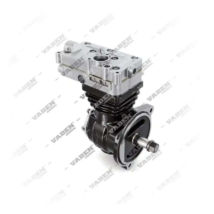
Need the part, not just the answer?
OE-grade air brake compressors and repair kits, manufactured and tested to commercial-vehicle standards.
Shop VADEN partsPublished by VADEN Original. Product links point to the manufacturer’s official catalogue. Specifications are general — always confirm figures against your vehicle’s service manual.