 airbrakecompressor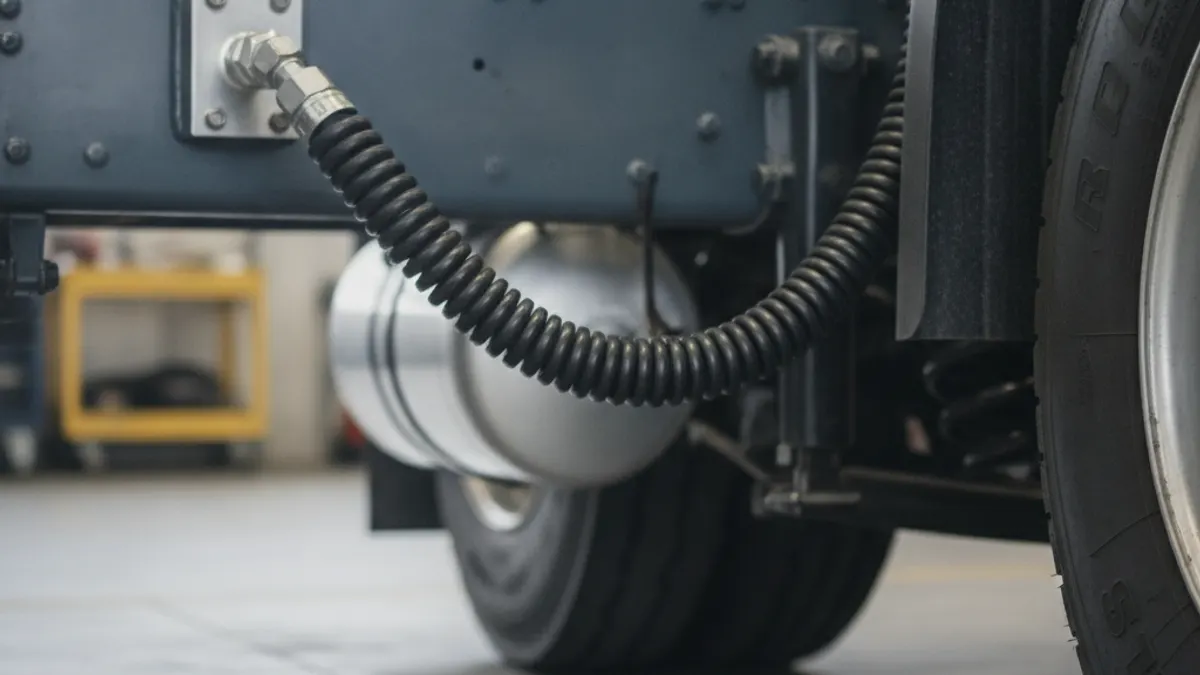
Air brake hoses and fittings are the pneumatic plumbing that carries compressed air from the compressor and reservoirs to every valve, brake chamber and trailer connection on the vehicle. Most of that plumbing is DOT-marked nylon tubing (SAE J844) joined with push-to-connect or compression brass fittings, plus reinforced rubber or thermoplastic hose (SAE J1402 / J1394) wherever a line has to flex — at the gladhands, across suspension travel and at the cab tilt. Every hose, tube, assembly and end fitting on the brake system must meet FMVSS 106 and carry a DOT marking; hardware-store air line and barbed splices are not legal repairs.
Types of air brake line and what each one is for
Three families cover almost everything on a truck or trailer. The lay line printed on the hose, or the stripe on nylon tubing, tells you which standard it was built to — read it before you replace anything.
| Line type | Typical standard | Where it is used | Notes |
|---|---|---|---|
| Nylon air brake tubing | SAE J844 | Frame runs, chassis-to-chamber, tank-to-valve plumbing | Typically rated around -40 F to 200 F; light and inexpensive, but no abrasion resistance on its own |
| Reinforced rubber air brake hose | SAE J1402 | Flex points, cab tilt, engine bay, gladhand pigtails | Textile-reinforced, oil and heat resistant; Type AI (light duty) and AII (heavy duty) |
| Thermoplastic air brake hose | SAE J1394 | Coiled tractor-trailer lines, flex points | Lighter than rubber, good abrasion resistance, holds coil memory |
| High-temperature discharge line | Manufacturer spec | Compressor discharge to the air dryer | Steel, braided or high-temp construction only — never nylon or standard rubber |
The compressor discharge line is the one people get wrong most often. It sees the hottest air in the system and must be routed with a continuous downward slope so condensate drains toward the dryer instead of pooling and freezing. When that line carbons up internally, the symptoms look exactly like a system that will not hold pressure.
Sizes and color coding
North American nylon tubing is sized by outside diameter in inches — 1/8, 1/4, 3/8 and 1/2 in are the common sizes, with 5/8 and 3/4 in used for large supply runs. European and many global-build chassis use metric OD: 6, 8, 10, 12 and 16 mm. The two look interchangeable and are not. Nominal 3/8 in tubing measures about 9.5 mm and will not seal reliably in a 10 mm push-to-connect fitting, so measure before you order.
As a rule of thumb, small-bore lines (1/8 to 1/4 in) feed control signals and gauges, 3/8 in feeds most service brake chambers and relay valve control ports, and 1/2 in and larger handles supply volume between the tanks, dryer and relay valves. Undersizing a supply line slows application and release timing even when nothing is leaking.
Body color is mostly a fleet convention, with one universal exception: at the tractor-trailer connection, red is the emergency/supply line and blue is the service line, and the gladhand couplers are keyed and colored to match. Crossing them defeats the tractor protection system, which is a safety defect rather than a nuisance.
Fittings: push-to-connect, compression and threaded
Push-to-connect (DOT push-lock) fittings dominate current production. A collet grips the tube, an O-ring seals it, and a release ring lets you pull the tube back out. They only work if the tube is cut square with a proper tubing cutter, deburred and pushed fully home. A tube cut at an angle with side cutters will pass a shop test and leak six months later.
Compression fittings use a brass sleeve and, on nylon, a tube support insert that goes inside the tubing. Leaving out the insert is one of the most common causes of a slow, intermittent leak: the nut crushes the tube and the joint relaxes as the plastic creeps.
Threaded connections into valves and chambers are usually NPT. Use a paste sealant or pre-applied dry sealant rather than PTFE tape, because shredded tape migrates downstream and hangs up relay and quick-release valve seats. Torque to the component maker's figure; brass fittings strip easily, and an overtightened port in an aluminum valve body is an expensive mistake.
Where air brake lines actually leak
| Leak point | How it shows up | Fix |
|---|---|---|
| Gladhand seals | Hiss at the coupling, pressure drop only when the trailer is hooked | Replace both seals as a pair; polyurethane seals last longer than plain rubber |
| Chafed tubing at a frame crossmember | Hiss under the truck, worn flat spot or exposed reinforcement | Replace the section, add a grommet or loom, re-clamp |
| Tube pulled from a push-to-connect | Sudden major leak, tube backed out of the fitting | Re-cut square, reinsert fully; replace the fitting if the collet is worn |
| Compression joint without insert | Slow leak that comes and goes with temperature | Fit the correct tube support and a new sleeve |
| Heat-hardened line near exhaust | Brittle, discolored tubing that cracks when flexed | Replace and reroute with clearance or shielding |
| Valve exhaust port hissing | Air escaping from a relay or quick-release valve, not a fitting | Internal valve seat — the line is not the problem |
To confirm a leak is real rather than normal system behavior, chock the wheels, build to governor cut-out (roughly 120 to 135 psi) and shut the engine off. With the brakes released, a straight truck should lose no more than about 2 psi in a minute and a combination no more than about 3 psi; with the service brakes applied and held, allow about 3 psi and 4 psi respectively. Anything above that needs to be found before the truck moves. On the restart, the governor should cut back in somewhere around 100 to 110 psi. The full sequence is covered in the air brake pre-trip inspection.
Routing and protection
- Support lines every two to three feet with proper clips or loom — unsupported runs whip and work-harden at the fittings.
- Keep bends generous. A common rule of thumb is a bend radius of at least six times the tube's outside diameter; tighter than that and the tube kinks or thins at the outside of the bend.
- Route away from exhaust, turbo housings and aftertreatment components, or use heat shielding. Nylon does not survive radiant heat.
- Never zip-tie a brake line directly to a wiring harness, fuel line or moving component, and leave slack for axle and cab movement.
- Cap open ports and blow lines out with clean, dry air before reassembly. Debris ends up in valve seats.
Replacing a line the right way
- Drain the system and confirm the gauges read zero. Chock the wheels; never rely on air pressure to hold the vehicle.
- Tag both ends before removal and route the new line along the original path, or a better one if the old path caused the failure.
- Cut tubing square with a tubing cutter, deburr the end, and match OD and standard exactly — DOT-marked material only.
- Fit new sleeves, inserts or fittings; do not reuse a collet or O-ring that let a tube pull out.
- Recharge, then leak-test with soapy water at every joint you disturbed and repeat the timed pressure-drop test above.
- Check that the low-air warning still activates around 60 psi and that the spring brakes apply as pressure falls into the 20 to 45 psi band.
Roadside inspectors treat air line defects seriously. Reinforcement showing through a hose cover, a bulge under pressure, a kinked or crimped tube, or an audible leak at a coupling can all put a unit out of service, and each of them is visible in a few minutes with a flashlight under the frame.
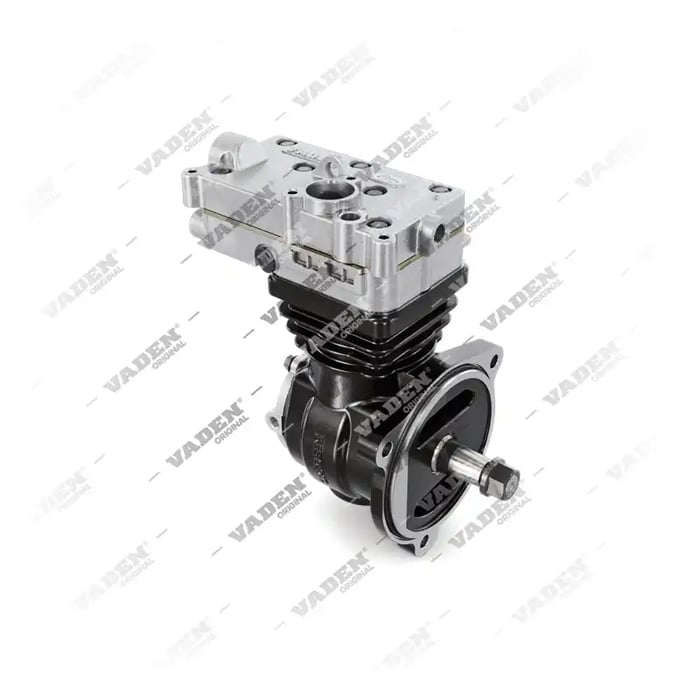
Need the part, not just the answer?
OE-grade air brake compressors and repair kits, manufactured and tested to commercial-vehicle standards.
Shop VADEN partsPublished by VADEN Original. Product links point to the manufacturer’s official catalogue. Specifications are general — always confirm figures against your vehicle’s service manual.