 airbrakecompressor
To replace an air compressor unloader kit, drain the air system to 0 psi, take the compressor to the bench and remove the unloader cover or cylinder head. Pull the old pistons, O-rings, guides and spring, clean and inspect the bores, then fit the new parts with the kit lubricant and new gaskets and tighten the fasteners in stages. Before refitting, leak-test the unloader port with regulated air, then confirm on the truck that the compressor unloads at governor cut-out and loads again at cut-in.
This page covers the bench procedure only. To confirm the unloader is really the fault, see how the compressor unloader valve works and fails; to match the kit to your compressor, see how to choose the correct unloader kit.
Before you start
- Make the vehicle safe. Park on level ground, chock the wheels, stop the engine and remove the key. Drain every reservoir, including any separate air dryer purge reservoir, until the gauges read zero. The spring brakes apply as pressure falls through roughly 20-45 psi; keep the wheels chocked anyway.
- Remove the compressor. With the engine cool, drain coolant below the head on water-cooled units and cap every air, oil and coolant line. The full sequence is in the air brake compressor replacement guide.
- Get the service data. Torque values, tightening order and leakage limits are model-specific. Some compressors, including certain WABCO twin-cylinder units, have no unloader kit at all; a leaking unloader there means a new cylinder head.
- Check the kit first. VADEN Original lists its OE-grade compressor unloader kits with the OE numbers they replace; confirm yours against the old unit before anything comes apart.
Identify the unloader layout
| Layout | Where the parts sit | Access | Typical kit contents |
|---|---|---|---|
| Block-mounted | Cylinder block, beneath the inlet valves (twin-cylinder Bendix Tu-Flo units, for example) | Remove the cylinder head and inlet valves | Pistons and O-rings, plungers and guides, saddle, spring seat, return spring |
| Head-mounted | A bore in the cylinder head under a spring-loaded cover (Bendix BA-921, for example) | Remove the cover | Piston and O-rings, balance piston, spring, cover and cover gasket |
| Integral | Built into the head with no separate service parts | Not serviceable as a kit | Complete cylinder head |
Removing the old parts
- Clean the outside of the compressor and scribe the head-to-block position. Grit that drops into an open unloader bore is what cuts new O-rings.
- Head-mounted: hold the cover down against its spring while removing the screws, then let it rise slowly. Block-mounted: remove the head bolts, break the gasket seal with a soft mallet rather than prying between machined faces, lift the head off, then remove the inlet valves, their springs and the valve guides.
- Remove the spring, saddle or balance piston and any spring seat, then the plungers, guides and pistons, laying them out in order. Note which way each piston faces; some carry an O-ring inside the top as well as in the outer grooves.
- Ease a stuck piston out with low-pressure regulated air at the unloader port, a rag over the bore and eye protection on. Never lever it with a screwdriver; a scored bore leaks with any kit.
- Remove O-rings with a non-metallic pick and discard every seal and gasket you disturb, even the ones that look good.
Cleaning and inspecting bores, pistons and seats
Wash reusable parts in commercial-grade solvent and dry them. Clear carbon from the inlet cavity and unloader passages, blow the passages through with shop air, and make sure any vent passage under the unloader cover is open. Clean gasket faces with a plastic scraper; a gouge in a sealing face is a leak no gasket will bridge.
| Check | What to look for | Action |
|---|---|---|
| Unloader bores | Scoring, pitting, corrosion or porosity | Replace the bore bushing if the design has one; otherwise the head, block or compressor |
| Old pistons | Heavy carbon on the seat or orifice | Points to heat or oil carryover; find the cause |
| Spring and spring seats | Old spring shorter than the new one; seat worn, loose or distorted | Always fit the kit spring; replace a damaged seat |
| Inlet valves | Binding in the guide, pitted or carboned seats | Service before closing up; each valve must be a loose sliding fit |
| Discharge cavity | Carbon heavy enough to restrict flow | Beyond an unloader kit; plan a fuller repair or replacement |
Fitting the new kit
- Compare each new part with the old one: piston length and diameter, O-ring groove positions and spring free length. A piston that looks close but seats differently will not hold the inlet valves open reliably.
- Coat the bores and O-ring grooves sparingly with the lubricant supplied in the kit; pistons that arrive pre-lubricated need nothing added. Do not substitute chassis grease unless the service data allows it.
- Roll each O-ring into its groove without twisting it, then push the piston squarely into its bore with a slight turn. Port edges cut O-rings; if a piston resists, pull it out and look before pushing harder.
- Move each piston through its stroke by hand. It must slide without binding; one that drags on the bench will stick in service.
- Block-mounted: fit the plungers in their guides over the pistons, set the spring seat in its locating hole in the inlet cavity, center the saddle forks on the guides and seat the spring over both spring seats, then refit the inlet valve guides and valves. Head-mounted: fit the spring into the piston, pass the balance piston through it, align the new cover gasket and hold the cover down while starting the screws.
Gaskets and torque sequence
Fit new gaskets dry unless the service data calls for sealant, and check orientation: many are not symmetrical, and where the unloader signal passes through the head gasket, one laid the wrong way round blocks it. Locate the head on its alignment pins or bushings, not on the bolts.
| Fastener | Tightening method |
|---|---|
| Unloader cover screws | Run in evenly while holding the cover against its spring; the specified torque is low, so use a wrench scaled for it |
| Head bolts, torque only | Snug all by hand, then tighten in a crossing pattern in two or three stages to the OEM value |
| Head bolts, torque plus angle | Initial torque in the numbered order, then each angle step in the same order with an angle gauge |
Small fasteners in aluminum strip easily, and a torque wrench at the bottom of its scale is inaccurate. Do not re-torque settled bolts unless the service data says to.
The unload test afterwards
On the bench. Connect the unloader port to a short hose, a gauge, a shut-off valve and a regulated air supply. Charge it to about cut-out pressure, roughly 120-135 psi and never above the service data figure, then close the valve. A steady needle means the seals hold; a falling needle means a leak, which soap solution on the cover joint and the inlet port will find.
On the truck. With the compressor refitted and a test gauge on the supply reservoir, build pressure: the compressor should stop building at cut-out, typically 120-135 psi, and a governor-signalled air dryer should purge at that moment. Draw pressure down with repeated brake applications; building should resume at cut-in, typically 100-110 psi. Run several cycles and check that each change is prompt. Then bring the system to cut-out, stop the engine and listen at the compressor inlet: escaping air means the unloader or discharge valves still leak.
If the compressor still will not unload, confirm signal air is reaching the port before blaming the kit; a faulty governor or a blocked or frozen signal line looks exactly like a failed unloader. Very frequent cycling with short unloaded periods points to a leaking seal in the new kit or a leak elsewhere in the system.
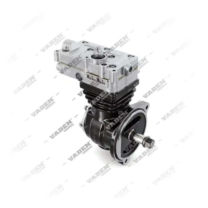
Need the part, not just the answer?
OE-grade air brake compressors and repair kits, manufactured and tested to commercial-vehicle standards.
Shop VADEN partsPublished by VADEN Original. Product links point to the manufacturer’s official catalogue. Specifications are general — always confirm figures against your vehicle’s service manual.