 airbrakecompressor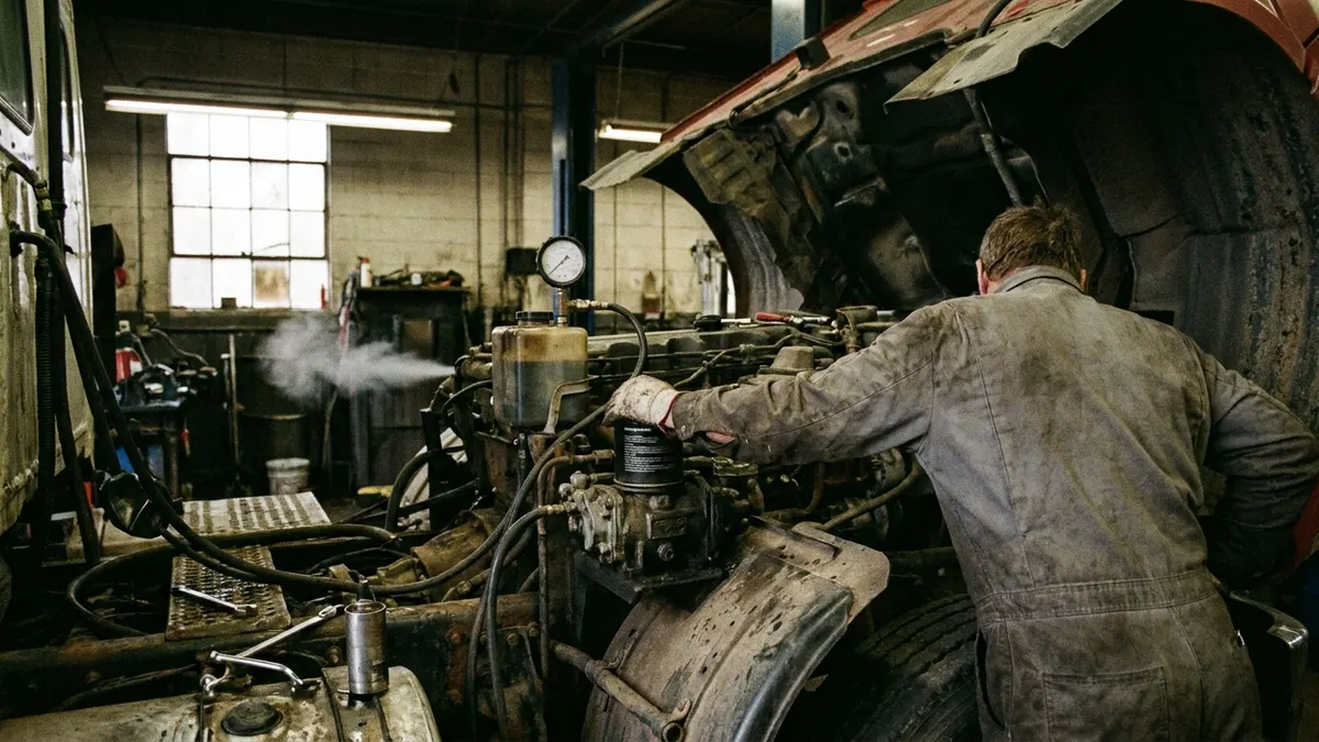
Replacing an air brake governor is a 30-to-60 minute job on most trucks. Drain the air system to zero, mark and disconnect the reservoir and unloader lines, unthread the governor from the compressor head or its firewall bracket, fit the new unit with fresh thread sealant, then build air and confirm the compressor cuts out in the 120-135 psi range and cuts back in around 100-110 psi. Replacement is a different job from adjustment: adjusting only moves the cut-out point of a governor that still works, while replacement is what you do when the unit leaks, sticks, or will not hold a setting.
Replace or adjust? Decide before you order the part
The governor is a pneumatic pressure switch. It senses reservoir pressure and, at cut-out, sends air to the compressor's unloader mechanism so the compressor stops pumping into the system. At cut-in it exhausts that signal and pumping resumes. On most units the cut-out point is adjustable at the cover screw, but the differential between cut-in and cut-out is preset internally and is not something you can dial in.
That preset differential is your decision line. If the system charges properly and simply cuts out a few psi high or low, follow the governor adjustment procedure first. Replace the governor when you see any of the following:
- Air leaking continuously from the governor's exhaust port with the system charged.
- The compressor never unloads, so pressure climbs until the safety valve pops — see governor not cutting out for the diagnosis path.
- Cut-in and cut-out points wander from one charge cycle to the next, or the differential has collapsed so the compressor loads and unloads every few seconds.
- The adjustment screw is seized, the cover is corroded through, or a port thread is stripped.
- The unit is contaminated with oil carried up the discharge line and the piston is gummed.
One caution before you spend money: a governor cannot cause low system pressure on its own if it is unloading correctly. If the truck is slow to charge, diagnose the compressor and supply side first. Fitting a governor to a worn compressor changes nothing.
Parts and tools
Match the replacement to the compressor and unloader design rather than to the shape of the old part. Bendix, Wabco/ZF, Knorr-Bremse and Midland units differ in port arrangement, mounting (direct head-mount versus remote bracket) and preset differential, and a physically similar unit can be set for a different pressure band. Quote by OE number from the compressor or the vehicle build, and cross-check against a supplier catalogue such as the compressor governor valve range from VADEN Original before ordering.
You will want: wheel chocks, two open-end wrenches to back up fittings, a socket set, pipe thread sealant rated for air brake service, replacement mounting gasket or O-ring if the unit is head-mounted, nylon tubing and fittings in case a line is damaged on removal, and a reliable dash or test gauge. A second gauge teed into the service reservoir is worth the trouble — dash gauges drift, and you are about to set a pressure band by one.
Step 1: Park, chock and depressurise
Park on level ground, chock the wheels, shut the engine down and apply the parking brakes. Now drain every reservoir — wet tank first, then primary and secondary, plus any auxiliary tank — until all gauges read zero and the drain valves stop hissing. Spring brakes apply somewhere in the 20-45 psi range as pressure falls, which is why the wheels are chocked and the truck is not going anywhere until you are finished.
Do not crack a governor fitting on a charged system. These are pneumatic lines carrying reservoir pressure, not hydraulic brake lines; a fitting released under load can whip and will fire debris.
Step 2: Mark the lines before you touch them
Most governors carry two air lines, and on many installations a third line is teed off the unloader signal to purge the air dryer. Tag each one with tape and a marker, and photograph the assembly. Reversing the reservoir and unloader connections is the classic mistake on this job and the fresh part gets blamed for it.
| Connection | Goes to | What happens if it is wrong |
|---|---|---|
| Reservoir (supply) port | Wet tank or supply reservoir | Governor never senses pressure; compressor runs continuously |
| Unloader port | Compressor unloader cavity | Compressor cannot unload; safety valve lifts |
| Purge signal tee (if fitted) | Air dryer purge valve | Dryer never purges; water and oil carry into the tanks |
| Exhaust port | Atmosphere (open, screened) | Blocked exhaust traps the signal; compressor stays unloaded |
Step 3: Remove the old governor
Back up each fitting with a second wrench so you twist the fitting and not the line or the compressor head. Cap or plug the open lines to keep grit out. Head-mounted governors come off with two cap screws and a gasket; remote units unbolt from a bracket. Inspect what comes out — oil pooled in the unloader line points at a compressor passing oil, and that fault will contaminate the new governor too, so deal with it while the lines are open.
Clean the mounting face completely. Old gasket material left on a head-mounted unit will hold the new governor off its seat and leak.
Step 4: Fit the new governor
Apply air-brake-rated thread sealant to the pipe threads only, keeping it back from the first thread so nothing migrates into the valve. Do not use PTFE tape on these ports if the manufacturer prohibits it; shredded tape is a contamination source. Fit the new gasket or O-ring dry unless the instructions say otherwise, start the fasteners by hand, and tighten to the manufacturer's figure for that unit — go by the service sheet, not by feel, and do not guess a torque value.
Reconnect the lines to the ports you tagged, keeping the exhaust port clear and pointing where it will not collect road spray. Make sure the adjustment cover is accessible with the unit mounted; you may need it in a moment.
Step 5: Build air and verify the settings
Close the drain valves, start the engine and let the system charge while you watch the gauge. Run the engine at fast idle and record the numbers over at least two full cycles.
| Check | Expected range | What you should hear or see |
|---|---|---|
| Cut-out | 120-135 psi | Gauge needle stops climbing; air dryer purges with a sharp exhaust |
| Cut-in | 100-110 psi | Compressor resumes pumping after brake applications draw pressure down |
| Normal running pressure | About 120 psi | Stable gauge reading with the system fully charged |
| Low-air warning | Around 60 psi | Buzzer and lamp during the pressure-drop test, then clear on recharge |
If cut-out sits outside the band, adjust it at the cover screw in small increments and recheck through a full cycle each time. Confirm the vehicle's own placarded specification where one exists — a bus or a specific chassis may be set tighter than the general range. The cut-in point follows the fixed differential; if it does not, the unit is wrong for the application or faulty out of the box.
Step 6: Leak check and finish
With the system charged and the engine off, spray soapy water on every fitting you disturbed and on the governor body seams. Nothing should bubble. Watch the gauges for a static leakage check over a couple of minutes, then apply the service brakes and watch again with the system loaded. Listen at the exhaust port: a steady bleed there with the system charged means the new unit is not seating and should not go into service.
Finish by draining the tanks once more to clear anything you introduced, then run a full pre-trip air check. Log the cut-in and cut-out figures you measured — the next technician needs a baseline, and a governor that has drifted away from a recorded setting is far easier to condemn than one with no history. For the underlying theory and fault patterns, keep the air brake governor reference alongside this procedure.
Need the part, not just the answer?
OE-grade air brake compressors and repair kits, manufactured and tested to commercial-vehicle standards.
Shop VADEN partsPublished by VADEN Original. Product links point to the manufacturer’s official catalogue. Specifications are general — always confirm figures against your vehicle’s service manual.