 airbrakecompressor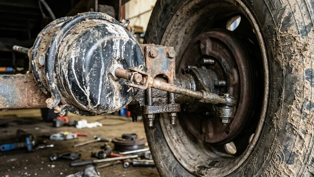
An MGM brake chamber is a conventional pneumatic double-diaphragm spring brake actuator: a service side that applies the brake with air, and a spring side that parks and emergency-applies the brake when air is lost. Two things set MGM units apart in the parts book and on the truck - the TR/TRLB part-number system, and e-STROKE, MGM's stroke-sensing option that reports brake adjustment from inside the chamber to a control module and a dash lamp. Everything else follows standard practice, so an MGM unit interchanges on the bracket when the sizes, stroke class, pushrod length and port arrangement all match.
MGM Brakes is a North American actuator manufacturer (a division of Indian Head Industries) supplying truck, trailer, bus and vocational chassis builders as original equipment, which is why you find its tags on units you did not order yourself.
How to read an MGM TR part number
The number stamped or printed on the tag breaks down into a family prefix, two size figures and a suffix block. The size figures are the effective diaphragm area of each side in square inches, and they follow the same industry convention every actuator maker uses.
| Element | Example | What it tells you |
|---|---|---|
| Family prefix | TR | Double-diaphragm spring brake actuator - service side plus power-spring side in one assembly |
| First two digits | 30 | Service side effective area in square inches (the side the foot valve pressurises) |
| Second two digits | 30 | Spring brake side effective area in square inches (park and emergency) |
| Long-stroke identifier | L in TRLB | Long-stroke service side - more usable travel, different readjustment limit |
| Suffix block | Letters and digits after the sizes | Pushrod length, port clocking, clevis and hardware variant - catalog-specific |
So a TR3030 is a 30/30 spring brake and a TRLB3030 is its long-stroke equivalent. The suffix block is where interchange goes wrong: two units with the same four digits can have different pushrod lengths and different port positions, and neither will bolt up correctly to the wrong axle. Read the whole number off the old unit before you order, and if the tag is unreadable, measure instead - pushrod length from the mounting face to the centre of the clevis pin hole, plus the clock position of the two air ports relative to the mounting studs. Our guide to identifying a brake chamber type covers the measurements in order.
Standard stroke versus long stroke
Long-stroke chambers give the slack adjuster more usable travel before the diaphragm runs out of stroke, which buys margin as linings wear. You can identify them without a catalog: a long-stroke service side carries a square air-inlet boss and a trapezoidal shape on the identification tag, both required markings. Standard-stroke units have a round boss and a rectangular tag.
This matters for two reasons. First, the two classes have different published readjustment limits, so an inspector measuring stroke needs to know which one is fitted - see how to measure pushrod stroke for the method. Second, you cannot mix classes across an axle. Both wheel ends must be the same size and the same stroke class, or the axle brakes unevenly. The differences are set out in full on our standard versus long-stroke chamber page.
e-STROKE: what it senses and what it reports
e-STROKE is MGM's brake monitoring system. A sealed sensor built into the chamber tracks the position of the pushrod through its travel, and a chassis-mounted control module interprets that movement and drives an indicator in the cab. Later generations can also report over the vehicle data bus rather than only through discrete lamps. The system watches for three distinct conditions.
| Reported condition | What the sensor saw | Usual root cause |
|---|---|---|
| Over-stroke | Pushrod travelled past its normal limit on application | Brake out of adjustment, worn linings, failed automatic slack adjuster, worn foundation components |
| Dragging | Pushrod did not return to its home position after release | Seized slack adjuster or camshaft, broken return spring, valve not exhausting, corroded pushrod or clevis |
| Non-functioning | No measurable movement when the brake was applied | No air reaching that chamber, broken pushrod or clevis pin, sensor or harness fault |
Treat the display as a pointer, not a verdict. A "non-functioning" report on one wheel end is just as likely to be a delivery line, a relay valve port or a pinched harness as it is the chamber itself, so confirm with a gauge at the chamber before condemning anything.
Wiring and diagnostic notes
Each monitored chamber carries a sensor lead that runs back to the control module, and the module takes switched power and a clean chassis ground. Take the pin-out from the harness diagram supplied with the kit rather than assuming a colour code - MGM has revised connector and harness detail across generations, and mixing components from different generations is the most common reason a freshly installed system will not initialise.
Three field habits save time. Keep the harness routed clear of the slack adjuster arc and the tyre throw pattern, because chafed leads produce intermittent faults that look like brake problems. Seal and support every connector rather than leaving it hanging where wash water collects. And when you replace one monitored chamber with a plain chamber, either fit the matching sensed unit or disable that channel deliberately - leaving a live lead unconnected will hold a fault on the dash indefinitely.
Finally, e-STROKE does not replace the physical measurement an inspector makes. Roadside and periodic inspections are done by measuring applied pushrod travel at the chamber with the system fully charged, and a monitoring lamp carries no weight in that check.
Service and safety points
The power spring in a spring brake actuator stores enough energy to apply the brake with no air in the system at all, and it stays dangerous after the unit is off the vehicle. Never cut, weld or drill a spring brake housing, and never split a non-serviceable assembly. Cage the spring with the release tool - many units carry it clipped to the housing - before disconnecting the clevis or pulling the chamber.
Remember also how the pneumatics behave when you are chasing a complaint. Spring brakes apply as system pressure falls into roughly the 20 to 45 psi band, the low-air warning should already be alerting by about 60 psi, and full release needs a properly charged system - around 120 psi, with the governor cutting out somewhere in the 120 to 135 psi range and cutting back in around 100 to 110 psi. A chamber that will not release on a truck sitting at low pressure is behaving exactly as designed. Build the system pressure first, then diagnose. The general operating principles for any make of actuator are covered on our brake chamber reference page.
Ordering and cross-referencing
When you cross an MGM number to a replacement, match five things in this order: service side size, spring side size, stroke class, pushrod length, and port clock position relative to the mounting studs. Then check the clevis and pin supplied, the mounting stud thread and spacing, and whether the original was a sensed e-STROKE unit. Get the first five right and the unit fits; get the last three wrong and you will be back under the truck for hardware. Where a chassis builder used MGM as original equipment, the OE number on the vehicle build sheet is usually the fastest route to a correct replacement.
Source (VADEN Original): Brake Chamber Types and Sizes: Choosing T, DD and Spring Chambers
Need the part, not just the answer?
OE-grade air brake compressors and repair kits, manufactured and tested to commercial-vehicle standards.
Shop VADEN partsPublished by VADEN Original. Product links point to the manufacturer’s official catalogue. Specifications are general — always confirm figures against your vehicle’s service manual.