 airbrakecompressor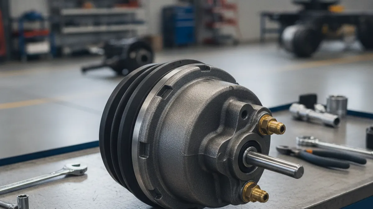
To identify an air brake chamber, read three things off the unit itself: the type number (9, 12, 16, 20, 24, 30, 36 — the effective diaphragm area in square inches), whether it is a service-only chamber or a spring brake combination (written as a pair, such as T30/30), and whether it is standard or long stroke. Those three facts, plus the mounting stud pattern and the air port positions, decide whether a replacement bolts up and works. Clamp band, clevis and pushrod length are details you confirm against the old part.
Where the identification lives on the chamber
Most chambers carry a stamped or riveted tag on the clamp band, the non-pressure housing, or the spring brake head. On a reasonably clean unit you will find some combination of type designation, maximum rated stroke, part number, and manufacturer name. On a road-salted chamber that has spent six years under a trailer, expect the tag to be unreadable or gone — which is why the measuring method further down matters.
Do not assume the chamber on the opposite side of the axle is the correct reference unless you know the vehicle has never been repaired. Mismatched chambers across an axle are a common cause of a truck that pulls under braking, so check both sides before you order.
Reading the type number
The type number is the effective area of the diaphragm in square inches, not a diameter and not a stroke figure. A Type 30 develops roughly 25 percent more output force than a Type 24 at the same air pressure, which is why fitting a larger chamber "for more braking" is not a repair — it changes the brake balance the chassis builder engineered and can put the axle outside its certified configuration.
| Type | Effective area (sq in) | Rated max stroke (in) | Typical readjustment limit (in) |
|---|---|---|---|
| 9 | 9 | 1.75 | 1 3/8 |
| 12 | 12 | 1.75 | 1 3/8 |
| 16 | 16 | 2.25 | 1 3/4 |
| 20 | 20 | 2.25 | 1 3/4 |
| 24 | 24 | 2.25 | 1 3/4 |
| 24 long stroke | 24 | 2.50 | 2 |
| 30 | 30 | 2.50 | 2 |
| 30 long stroke | 30 | 3.00 | 2 1/2 |
| 36 | 36 | 3.00 | 2 1/4 |
Treat the limit column as a working reference and verify it against the current out-of-service criteria and the vehicle maker's service data before you pass or fail a brake. Our brake adjustment limits chart covers the full table, including bolt-type and rotochamber styles.
Single chamber or spring brake: decoding T30/30
A single number, for example "Type 24", means a service-only chamber: air in, pushrod out, no parking function. Steer axles typically use these.
A pair of numbers means a spring brake, sometimes called a piggyback or tandem chamber, used where the axle must also provide parking and emergency braking — normally drive and trailer axles. The first number is the service section (the side that responds to the foot valve) and the second number is the spring, or parking and emergency, section. So a T30/30 has a Type 30 service side and a Type 30 spring side, while a 24/30 pairs a Type 24 service side with a Type 30 spring housing. Mixed sizes are common on tractor drive axles, so read both numbers — ordering a 30/30 where the truck wants a 24/30 changes the service side output.
Visually, a spring brake has two air ports and a caging (release) bolt, usually stowed in a pocket on the side of the housing. A service-only chamber has one port and no caging bolt. Before you disturb one, read how to cage a brake chamber.
Safety: the power spring in a spring brake section stores enough energy to kill. Never cut, torch, or open a spring brake housing, and never remove a chamber from its bracket without caging the spring or confirming the unit is a sealed non-serviceable type that must be scrapped intact.
Standard stroke versus long stroke
Long-stroke chambers provide more usable stroke before the brake runs out of travel, and they are not interchangeable with standard-stroke units for compliance purposes, because the allowable pushrod travel is different. The usual identification cues:
- Square air inlet ports — the widely used industry convention for a long-stroke service chamber, versus round or hex bosses on standard-stroke units.
- Stroke marked on the body or tag — "2.5" or "3.0" stamped near the type number.
- Trapezoidal or specially shaped ID tag, used by several manufacturers to flag long stroke.
- Overall length — a long-stroke unit is physically deeper than the same type in standard stroke.
If two cues disagree, trust the stamped stroke rating over the port shape and confirm against the manufacturer's catalogue listing for that part number.
What the type number does not tell you
Two chambers can both be genuine Type 30/30 units and still not interchange. Before ordering, capture:
- Mounting stud pattern — number of studs, centre-to-centre spacing, thread size and stud length. Long studs are used where the chamber mounts through a thick bracket.
- Port position (clocking) — the angular position of the air ports relative to the mounting studs, listed by manufacturers as a numbered or clock position. Get it wrong and the airlines foul the frame or the slack adjuster.
- Port thread size — commonly 1/4 or 3/8 in NPT on North American units, metric on many European chassis.
- Pushrod length and thread, and whether the rod comes cut to length or with a clevis fitted.
- Clamp-type versus sealed — clamp band units accept a diaphragm and hardware kit; welded or crimped units are replace-only.
- Disc or drum — air disc brake actuators mount to the caliper and are a different family from S-cam foundation brake chambers, so do not cross them by type number alone.
If the tag is gone: identify it by measurement
- Chock the wheels, drain the system or cage the spring brake, and disconnect the airlines.
- Measure the outside diameter of the clamp band or housing and compare it with the manufacturer's dimension table; diameter steps up predictably with type, which is the quickest way to separate a 24 from a 30.
- Measure and record stud spacing, stud diameter and thread, and stud length above the bracket face.
- Note port shape (square versus round), thread size, and the position of each port relative to the studs. Photograph the unit on the vehicle before removal.
- Measure the exposed pushrod length at full release and the clevis pin diameter.
- Compare with the opposite side of the axle as a sanity check only, then cross-reference a supplier catalogue by dimension rather than by guess.
With those figures you can specify a replacement confidently from an OE-grade supplier — VADEN Original lists chambers alongside the rest of its commercial vehicle brake system components by dimension and application, which is what you need when the tag is unreadable.
Before you fit the new one
Replace chambers in axle pairs where possible, match stroke type across the axle, and reset slack adjuster travel after fitting. Then run a static and applied leak check and measure pushrod stroke with the system charged to roughly 90 to 100 psi, engine off, at full application.
Need the part, not just the answer?
OE-grade air brake compressors and repair kits, manufactured and tested to commercial-vehicle standards.
Shop VADEN partsPublished by VADEN Original. Product links point to the manufacturer’s official catalogue. Specifications are general — always confirm figures against your vehicle’s service manual.