 airbrakecompressor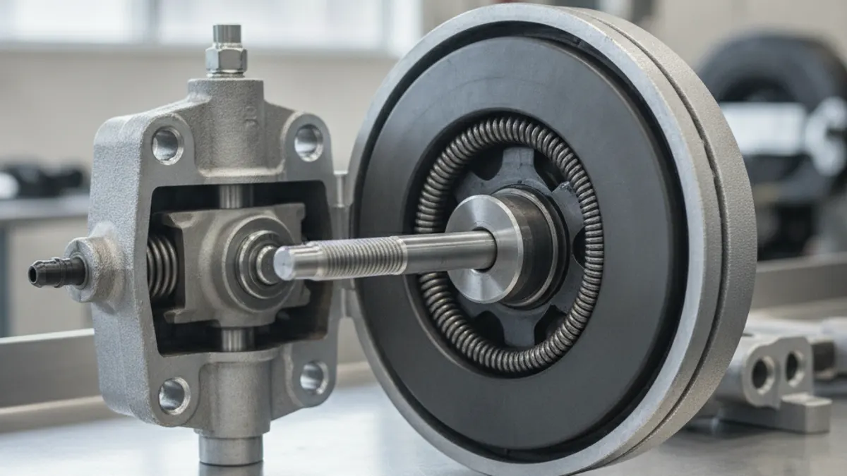
A brake chamber diagram shows two things stacked together: a service chamber that turns air pressure into pushrod force for normal stops, and, on drive and trailer axles, a spring brake chamber bolted to the back of it that does the opposite — it uses a large coiled power spring to apply the brake when air is lost or deliberately exhausted. Air enters the service port, presses on a rubber diaphragm, and pushes a pushrod out; the pushrod swings the slack adjuster, which rotates the S-cam and forces the shoes against the drum. Everything else in the chamber exists to seal that air, guide that rod, or contain that spring.
One point the diagram makes clear straight away: this is a purely pneumatic actuator. There is no fluid, no master cylinder and no hydraulic line involved, so anything wet on the housing is water or road spray finding its way in. Below is the labelled walkthrough, half by half, followed by what each part looks like when it fails.
The service brake chamber, front to back
Picture the chamber cut in half lengthwise, mounting bracket on the left, pushrod exiting toward the slack adjuster.
| Part | Where it sits | Job |
|---|---|---|
| Pressure plate / non-pressure plate | The two stamped steel halves of the housing | The pressure (air side) half carries the service port; the non-pressure half carries the mounting studs and the pushrod opening |
| Diaphragm | Clamped between the two halves | Fabric-reinforced rubber disc that seals the air chamber and converts pressure into linear force |
| Clamp ring (band clamp) | Around the joint between the halves | Two half-rings and bolts that squeeze the housing onto the diaphragm bead |
| Pushrod plate | Against the dry side of the diaphragm | Spreads diaphragm load evenly into the rod so the rubber is not point-loaded |
| Pushrod | Through the non-pressure plate | Carries force out to the clevis and slack adjuster |
| Return spring | Around the pushrod, inside the housing | Light spring that retracts the rod and diaphragm when air is exhausted |
| Clevis, clevis pin, jam nut | End of the pushrod | Adjustable joint linking rod to slack adjuster; the threaded clevis position sets rod length and the jam nut locks it |
| Service port and breather/drain | Pressure half; lowest point of non-pressure half | Air in; water and road spray out |
Chamber size is the effective diaphragm area in square inches — a Type 30 has roughly 30 in² of working area. Double the area and you roughly double the output force at the same pressure, which is why swapping chamber sizes across an axle is never a field improvisation. Size and stroke are covered in more detail on the chamber sizes page.
The spring brake half (the piggyback)
Bolted behind the service chamber is a sealed canister with its own diaphragm or piston and a large, heavily coiled power spring. In the diagram it looks like a second chamber facing the opposite direction, and functionally that is exactly what it is.
- Power spring — stores enough mechanical force to apply the brake with no air in the system. This is the parking and emergency brake.
- Spring-side diaphragm or piston — when the hold-off (emergency) port is charged, air compresses the spring and holds it back.
- Actuator rod and centre seal — the spring pushes this rod forward, which in turn drives the service pushrod out.
- Release stud (caging bolt), washer and nut — a threaded stud that mechanically winds the power spring back so the brake can be released with no air.
- Clamp band — on modern chambers the spring section is welded or crimped and is not serviceable. Only older designs use a bolted band, and those are the dangerous ones.
Safety: never cut, grind or unbolt the band on a spring brake canister. A compressed power spring can release with enough force to cause serious or fatal injury. Cage it first with the release stud, or replace the whole piggyback as a sealed unit — see how to cage a brake chamber.
How the two halves behave at different pressures
Reading a diagram is easier when you map it to what the gauges are doing. Exact thresholds vary by valve, vehicle and market, so treat the figures below as typical ranges rather than specification values, and use the vehicle manufacturer's current service manual for anything you intend to set or condemn against.
| System pressure | Spring side | Service side |
|---|---|---|
| Fully charged, around 120 psi | Power spring fully held off by air, brake released | Applies and releases with pedal demand |
| Governor cycling: cut-in around 100–110 psi, cut-out around 120–135 psi | No change | No change; only the compressor loads and unloads |
| Around 60 psi | Still held off, but the margin is gone | Low-air warning light and buzzer active — stop and fix it |
| Roughly 20–45 psi | Power spring overcomes the remaining air; brakes apply automatically | Little or no usable service braking left |
| 0 psi (parked) | Fully applied mechanically | Idle |
Because both halves act on the same rod, a chamber that will not release can be a spring-side problem — no hold-off air, or corroded internals — rather than a foundation brake problem. Working out which half is at fault before you pull the wheel saves a lot of time.
Ports and plumbing on the diagram
A combined chamber has two air connections and at least one vent:
- Service port — fed from the relay valve; pressure rises and falls with pedal application.
- Emergency / hold-off port — constant supply from the park control circuit; exhausting it applies the spring brakes.
- Breather or drain hole — must point down and stay open, otherwise the chamber traps water and the pushrod rusts.
Reversing the two lines during a chamber swap is a classic error: the brake drags or refuses to release, and the park control does not behave as expected. Label both hoses before you pull them.
What each part looks like when it fails
- Diaphragm — pinholes or a split along the flex line. Symptom: audible leak at the chamber, long stroke, pressure loss on an applied leak test.
- Clamp ring — corrosion or loose bolts letting the diaphragm bead weep air around the seam.
- Return spring — weak or broken, so the rod drags back slowly and the shoes stay lightly applied.
- Pushrod and clevis — bent rod, worn clevis pin, loose jam nut. All of these show up as excessive or inconsistent stroke at the slack adjuster.
- Power spring — broken coil from corrosion. The brake may not park properly, or you hear a bang and find the chamber dead.
- Release stud — seized in the housing, so the chamber cannot be caged for towing. Very common on high-mileage trailers.
- Housing — rust-through at the drain hole, usually on units that have spent winters in salt.
A quick field check: charge the system fully, chock the wheels, have someone hold a full application, and go under with a soapy spray bottle. Bubbles at the seam or the rod opening condemn the chamber. Then release the springs and check that every rod pulls fully home.
Chambers are replaced in matched pairs across an axle, same type and same stroke rating, so both wheel ends produce the same force at the same pressure. If you are ordering, keep the type number, stroke and port sizes together with the rest of your OE-grade air brake system components so the whole wheel end stays consistent.
Once you can read the diagram, the rest of the wheel end follows: pushrod stroke tells you about adjustment, adjustment tells you about the slack adjuster, and the slack adjuster tells you about the cam and linings behind the drum. The brake chamber overview ties those pieces together.
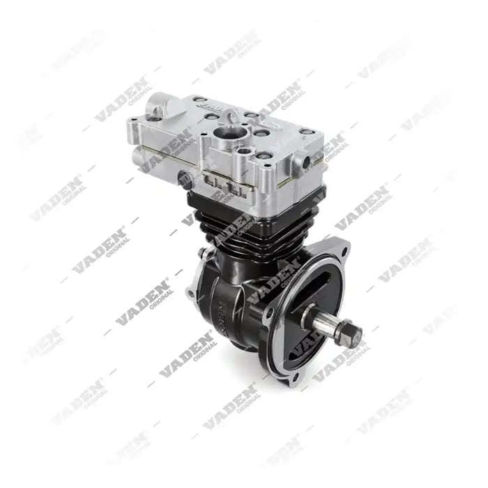
Need the part, not just the answer?
OE-grade air brake compressors and repair kits, manufactured and tested to commercial-vehicle standards.
Shop VADEN partsPublished by VADEN Original. Product links point to the manufacturer’s official catalogue. Specifications are general — always confirm figures against your vehicle’s service manual.