 airbrakecompressor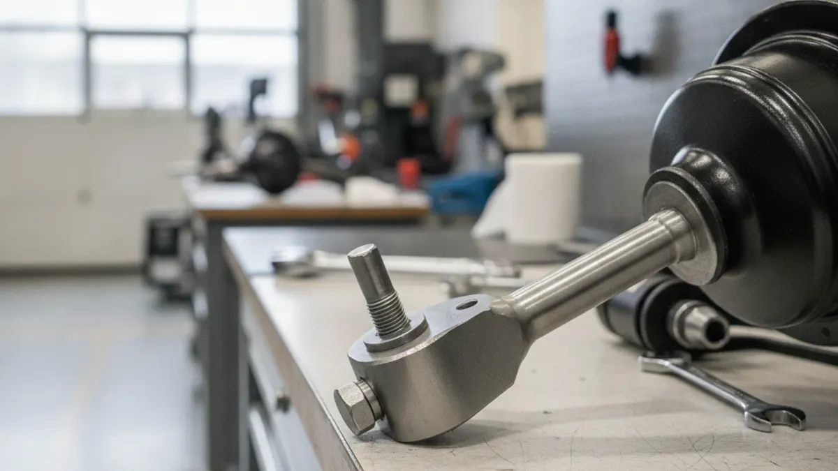
The brake chamber clevis is the forked steel fitting that threads onto the end of the chamber pushrod and pins to the slack adjuster arm. It turns the straight-line push of the air-operated diaphragm into rotation of the slack adjuster, which twists the S-cam and forces the shoes against the drum. Get clevis position, pushrod length or pin condition wrong and you lose stroke, lose force, and eventually fail an inspection.
The setup rule that matters most: the pushrod should form as close to a 90-degree angle with the slack adjuster arm as possible at full brake application - not with the brakes released. That is where mechanical advantage peaks, and that is where you need it.
What the clevis and pushrod do
This is a purely pneumatic linkage, with no hydraulic fluid anywhere in it. Air pressure acts on a diaphragm backed by a pressure plate, and that plate drives the pushrod out of the chamber. The clevis sits on the rod's threaded end, and a clevis pin through the clevis yoke connects it to a hole in the slack adjuster arm. As the rod extends, the arm swings and the camshaft rotates.
Three things depend on that geometry:
- Effective lever arm - the perpendicular distance from the camshaft centreline to the pushrod line of action; it peaks when the rod is perpendicular to the arm.
- Available stroke - how far the rod travels before the diaphragm bottoms out. Free play in a worn linkage eats into it.
- Return - the chamber return spring has to pull everything back. A binding or misaligned rod is a common reason a brake chamber is slow to release.
Clevis thread and pin sizing
Clevises are not universal. The thread cut on the pushrod dictates the clevis, and the pin diameter and yoke width have to suit the slack adjuster arm. The combinations you will meet most often:
| Pushrod thread | Typical application | Pin size class | Notes |
|---|---|---|---|
| 1/2"-20 UNF | North American service and spring brake chambers | 1/2" (about 12.7 mm) | Most common standard-duty thread |
| 5/8"-18 UNF | North American heavy-duty and long-stroke chambers | 5/8" (about 15.9 mm) | Used where rod loads are higher |
| M16 x 1.5 | European truck, bus and trailer chambers | 16 mm class, varies by OE | Will not interchange with UNF |
Confirm the thread against the chamber manufacturer's catalogue or the OE part number rather than eyeballing it - a 1/2"-20 clevis started on an M16x1.5 rod will feel like it is threading for a turn or two, then strip. VADEN Original's commercial vehicle brake system parts range lists chambers and related components by OE reference, which keeps thread, pin and yoke dimensions matched.
Setting correct pushrod length
Length is set by how far the clevis is threaded onto the rod. Two requirements compete, and a correct setting satisfies both:
- Released - with the brakes released and the system fully charged (around 120 psi; governor cut-out normally falls in the 120-135 psi band), the pushrod should be essentially fully retracted. A rod sitting partly extended at rest has already spent part of its stroke budget.
- Applied - at full application the rod should be at or very near 90 degrees to the slack adjuster arm.
On the vehicle:
- Chock the wheels, build to full pressure and release the parking brakes. Cage the spring brake on a combination chamber.
- Back off the slack adjuster, then thread the clevis on until the pin holes in the clevis and slack arm line up with the rod fully retracted.
- From there, most manufacturers call for backing the clevis off a small amount - typically on the order of half a turn to a turn - so the linkage is not holding the rod extended. Use the published figure, not a rule of thumb.
- Fit the clevis pin and retainer, then tighten the locknut hard against the clevis body so the setting cannot drift.
- Adjust the brake, or let an automatic slack adjuster take up slack over several full applications, then measure applied stroke with reservoir pressure in the usual 90-100 psi measuring band.
If the geometry will not come out - the rod sits at a clearly wrong angle at apply, or you run out of thread - the cause is usually the wrong chamber, the wrong hole in the slack arm, or an arm of the wrong length. Moving the clevis will not fix a wrong-length arm. See the slack adjuster adjustment guide for how arm length interacts with stroke.
Worn clevis pins: the hidden cause of excess stroke
The pin runs in the two clevis yoke holes and in the slack arm hole. Under repeated load reversals, with grit and moisture in the joint, the pin wears into an hourglass shape and the holes elongate into ovals. Every thousandth of wear becomes lost motion - the rod moves before the cam does. Wear in three locations adds up to enough free play to push a marginal brake past its adjustment limit, even with a healthy slack adjuster.
If a brake reads long on stroke but the slack adjuster is confirmed to be adjusting, pull the clevis pin and inspect it before condemning anything else.
Inspection checks
- Pin condition - roll it on a flat surface. Visible taper, a flat spot or waisting means replace it.
- Hole shape - a round hole gone oval is a replacement item, not something to ream out or weld up at the roadside.
- Free play - with the brakes released, pry the slack arm by hand in the applied direction. Movement before the cam turns is lost motion in the linkage.
- Retainer - cotter pins and clips are single-use, and a missing one can drop the linkage entirely.
- Rod and boot - a bent pushrod means impact or binding, so replace the chamber rather than straightening it. A split boot lets water and salt in, and the rod seizes.
Replacing the clevis and pin
Never work under a chamber with an uncaged, unrestrained power spring.
- Chock the wheels, secure the vehicle and follow safe practice for caging the spring brake chamber before disturbing any linkage.
- Remove the retainer and drive out the old pin. Corroded pins may need penetrating oil; do not hammer on the slack arm itself.
- Loosen the locknut and unthread the clevis, counting exposed threads as a reference.
- Wire-brush and inspect the pushrod threads. Damaged threads mean chamber replacement, not a chased thread.
- Fit the new locknut and clevis, setting length by the procedure above, then install the new pin, new bushings if the design uses them, and a new retainer. Many designs call for a light film of lubricant only, since heavy grease traps abrasives.
- Torque the locknut against the clevis to the manufacturer's figure. That is what holds the length setting.
- Adjust the brake, measure applied stroke, and confirm it is within the limit for that chamber type and size. Repeat on the opposite wheel end so the axle stays balanced.
Symptoms that point back to the linkage
| Symptom | Likely linkage cause | Check first |
|---|---|---|
| Long stroke on one wheel only | Worn pin or elongated holes on that corner | Pull the pin; test for lost motion |
| Weak braking, stroke reading acceptable | Poor angle at apply, rod far from 90 degrees | Arm length, hole choice, clevis position |
| Slow release, mild drag | Rod held extended at rest, or binding linkage | Clevis threaded on too far; boot; corrosion |
| Clunk or knock on application | Excessive free play in the pin joint | Retainer present? Pin diameter against hole |
| Imbalance across an axle | Different clevis settings side to side | Compare both sides physically, not by feel |
The clevis, pin and locknut are the parts most often reused because they looked fine. Replace them with the chamber, set the length properly, aim for 90 degrees at apply, and verify with a stroke measurement before the wheels turn.
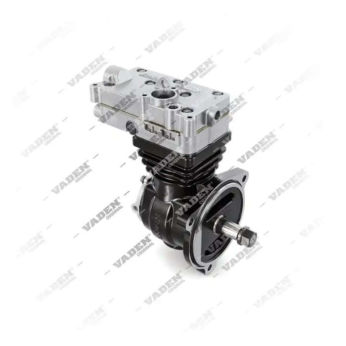
Need the part, not just the answer?
OE-grade air brake compressors and repair kits, manufactured and tested to commercial-vehicle standards.
Shop VADEN partsPublished by VADEN Original. Product links point to the manufacturer’s official catalogue. Specifications are general — always confirm figures against your vehicle’s service manual.