 airbrakecompressor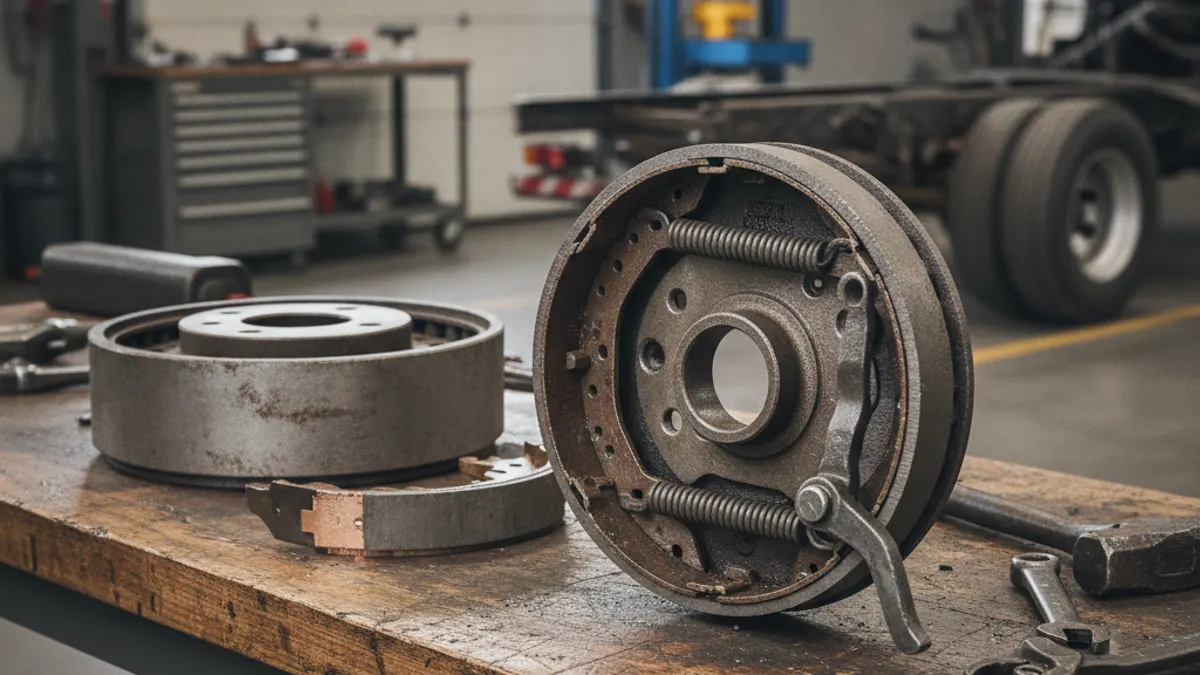
A truck drum brake diagram shows the S-cam foundation brake laid out around the wheel end: air pushes the brake chamber pushrod out, the pushrod swings the slack adjuster, the slack adjuster rotates the camshaft, and the S-shaped cam head at the far end spreads two brake shoes outward until the linings contact the inside of the drum. Everything else on the drawing — anchor pins, cam rollers, return springs, the spider, bushings and retainers — exists to locate those shoes, let them move freely, and pull them back when the air is released.
How to orient yourself on the diagram
Picture the wheel end with drum and hub pulled off, looking inboard. You are looking at a flat plate — the spider, also called the brake carrier or torque plate — bolted to the axle housing flange. Two curved brake shoes sit on that plate facing each other, forming a circle just inside where the drum will go.
Each shoe has two ends. At one end both shoes sit on anchor pins, where they pivot and stay put. At the other, both shoes carry a cam roller, with the S-cam head between the two rollers like a wedge. The shoe return springs stretch between the shoes and hold them collapsed inward against the cam. That is the whole geometry.
Part-by-part key to the diagram
| Part | Where it is on the diagram | What it does |
|---|---|---|
| Brake chamber | On a bracket on the axle, beside the spider | Converts air pressure into linear pushrod force |
| Pushrod and clevis | Between chamber and slack adjuster | Transfers chamber force; the clevis pin is the wear point |
| Slack adjuster | Lever splined onto the outer end of the camshaft | Turns push into rotation and takes up lining wear |
| Camshaft | Long shaft in a tube on the axle housing | Carries rotation from slack adjuster to cam head |
| Camshaft bushings and seal | One in the spider, one in the support bracket | Support the shaft and keep grease in, water out |
| S-cam head | Between the roller ends of the two shoes | Spreads both shoes outward as it rotates |
| Cam rollers and retainers | In the forked ends of each shoe | Let the cam profile slide with low friction |
| Brake shoes (web and table) | The two curved steel arcs | Carry the lining and transmit torque to the anchor pins |
| Linings with rivets or bolts | Friction blocks on the outer face of each shoe | Convert motion into heat |
| Anchor pins and bushings | Opposite end of the shoes from the cam | Fixed pivot point for each shoe |
| Return springs | Stretched between the two shoe webs | Pull the shoes off the drum on release |
| Spider (carrier) | Plate bolted to the axle housing flange | Holds anchor pins and camshaft bushing; reacts brake torque |
| Brake drum | Fits over the whole assembly at the hub | Friction surface and heat sink |
| Dust shield | Ring between spider and drum edge | Keeps road spray and debris off the linings |
What moves during an application
Follow the arrows on the diagram in this order:
- The driver presses the treadle valve, and service air fills the brake chamber behind the diaphragm.
- The diaphragm pushes the pushrod out; stroke grows as linings wear, which is why inspectors measure it.
- The pushrod swings the slack adjuster through an arc, rotating the camshaft — well under a quarter turn even at full application.
- The S-cam head rotates. Its rising profile pushes both cam rollers apart at the same time.
- Each shoe pivots on its anchor pin, swinging its lining outward against the drum. Both shoes are driven by the cam, which is what separates an S-cam brake from a duo-servo car brake.
- Friction between lining and drum resists rotation. That torque feeds back through the shoe web into the anchor pin, the spider and the axle.
- Kinetic energy leaves as heat through the drum. On a long grade, drum temperature rather than pedal effort becomes the limiting factor.
What moves on release
Release is purely mechanical. When air exhausts, the chamber return spring retracts the pushrod and the shoe return springs pull the shoes back in against the cam. Nothing pushes the shoes off the drum — they are pulled. If a return spring is stretched or broken, an anchor pin is rusted into its bushing, or the camshaft is seized in a dry bushing, the shoes stay in light contact and you get a hot drum, a burnt smell and a pull to one side. Chase brakes that will not release through those three items before you blame a valve.
Shoes, linings and drum sizes
Most North American heavy-truck foundation brakes are 16.5 in diameter. Steer axles typically run a 7 in wide shoe; drive and trailer axles usually run 8-5/8 in. A 15 in diameter brake still turns up on some trailers and vocational axles. When you read a diagram to order parts, the numbers you need are drum diameter, shoe width, and whether the linings are riveted or bolted.
Lining thickness matters as much as compound. Fleets normally order matched brake lining and shoe kits so both wheel ends on an axle share the same friction code — mixing codes side to side is a classic cause of pulling under a hard application. Some axle specifications call for different friction material on the leading and trailing shoe, which is why a diagram can show two part numbers for what look like identical shoes. Compounds and wear limits are covered in the guide to truck brake shoes and linings.
Drums carry a maximum diameter cast or stamped into them, commonly 0.120 in over nominal. Machine to the drum's own limit, never to a number you remember from another job.
Wear points the diagram quietly warns you about
| Component | Symptom on the truck | What you find at teardown |
|---|---|---|
| Camshaft bushings | Uneven lining wear, cam head cocked | Visible radial play when you lever the cam head |
| Cam rollers | Long stroke that returns after a few applications | Flat spots, blued rollers, dry retainers |
| Anchor pins and bushings | Dragging, tapered lining wear | Rust-locked pins, shoe will not rock freely |
| Return springs | Hot drum with the pedal released | Stretched coils, broken hooks |
| Clevis pin and slack bores | Lost motion, longer than expected stroke | Egg-shaped holes, sloppy pin fit |
The two most common roadside violations at this wheel end are lining thickness and pushrod stroke. Stroke limits depend on chamber type and size — a standard clamp-type 30 and a long-stroke 30 do not share the same limit — so identify the type stamped on the housing and measure against the limit for that chamber.
Where this brake sits in the wider system
The foundation brake is only the last few inches of a long air path: compressor, governor, air dryer, reservoirs, foot valve, relay valve, and finally the chamber on the diagram above. On a healthy system the governor cuts the compressor out around 120-135 psi and cuts it back in around 100-110 psi, a fully charged system sits near 120 psi, and the low-air warning comes on at about 60 psi. A mechanically perfect brake will still stop poorly if supply pressure sits low or a relay valve is slow, and no amount of valve work fixes a seized camshaft. Use the diagram to decide which half of the system you are in, then work that half. The overview of S-cam foundation brakes covers how torque output changes with chamber size, slack adjuster length and drum diameter — the three numbers that set braking force at each wheel.
Rule of thumb: if both shoes are worn evenly and the drum is clean, look upstream at air supply. If one shoe, wheel or axle stands out, the fault is mechanical and it is on this diagram.
Need the part, not just the answer?
OE-grade air brake compressors and repair kits, manufactured and tested to commercial-vehicle standards.
Shop VADEN partsPublished by VADEN Original. Product links point to the manufacturer’s official catalogue. Specifications are general — always confirm figures against your vehicle’s service manual.