 airbrakecompressor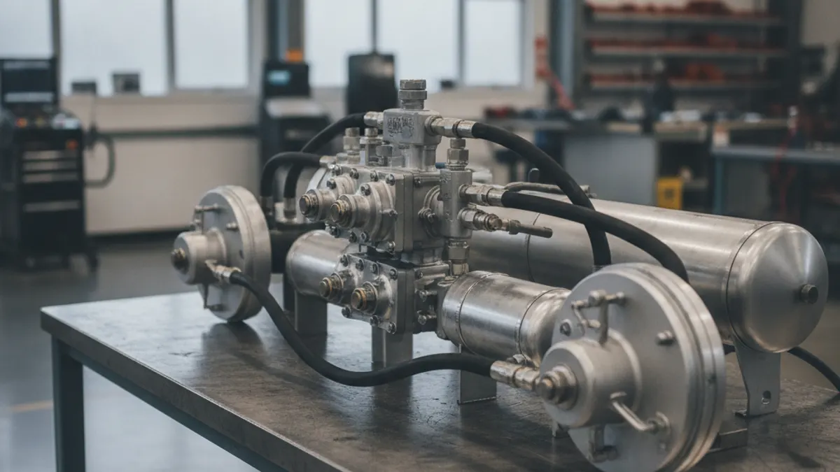
A truck air brake system diagram shows compressed air moving in one direction through three linked sections: a supply circuit that makes, dries and stores the air, a dual service circuit that meters it to the wheels when you press the pedal, and a parking and trailer circuit that holds the spring brakes released. Air is produced by an engine-driven compressor, regulated by a governor, dried and stored in reservoirs, then released through the foot valve and relay valves into the brake chambers, where pneumatic pressure becomes mechanical force at the foundation brakes.
Unlike a car's hydraulic brakes, nothing in this circuit is a sealed column of fluid. Air is compressible and slow to move, so the whole layout is built around storing pressure close to where it will be used and signalling valves to release it locally.
Section 1: the supply circuit
Follow the diagram from the engine outward. The compressor is gear- or belt-driven off the engine and turns whenever the engine runs. Its discharge line carries hot, wet, oil-bearing air to the air dryer, which strips out moisture and oil aerosol before the air reaches storage. From the dryer, air enters the first reservoir, the wet tank (also called the supply tank), where any remaining condensate settles at the bottom.
The governor is the control brain of this section. It senses reservoir pressure and, at cut-out, signals the compressor's unloader to stop pumping and simultaneously purges the dryer. When pressure falls to cut-in, the governor re-loads the compressor. On a typical heavy truck, cut-out sits around 120-135 psi and cut-in around 100-110 psi, with a fully charged system running near 120 psi. Treat these as ranges, not settings: the chassis manufacturer's service data is what governs your vehicle.
Downstream of the wet tank sits a multi-circuit or pressure-protection valve. This is the split point on the drawing: it feeds the primary and secondary reservoirs plus the park and trailer branch, and it protects the supply side so a burst line in one branch cannot bleed the whole truck dry. A one-way check valve at each reservoir inlet does the same job in reverse, trapping stored air if the line upstream fails.
The air dryer is the component most often left off simplified drawings and the one most responsible for system health: wet, oily air ruins valve seals, rusts tanks and freezes lines in winter.
Section 2: the dual service circuits
From the primary and secondary dry tanks, two independent delivery paths run to the foot valve, also called the treadle valve. This is the heart of a dual air brake system: two separate circuits, usually primary to the drive axles and secondary to the steer axle and, through the trailer supply, to the trailer, so a failure in one still leaves usable braking.
Press the pedal and the foot valve does not push air all the way to the wheels. It sends a metered signal pressure down a small-diameter line to the relay valves. Each relay valve sits close to its axle group and is fed by a large hose from the nearby reservoir. When it sees the signal, it opens a big port and dumps local tank air straight into the brake chambers, then exhausts that air to atmosphere on release. The relay valve's exhaust is the hiss you hear under the truck.
Inside the chamber, air pushes a diaphragm against a pushrod. The pushrod moves the slack adjuster, the slack adjuster rotates the S-cam, and the cam spreads the shoes against the drum. Pressure in, torque out.
Section 3: the parking and trailer circuit
Spring brakes work backwards from service brakes. A heavy coil spring in the rear half of the chamber applies the brake mechanically; air pressure in that half compresses the spring and holds the brake off. So the diagram shows a permanent hold-off line running from the dash park control valve, the yellow diamond knob, to the spring side of every parking chamber.
Pull that knob, or let pressure drop far enough, and the hold-off air exhausts. The springs then apply, typically beginning somewhere in the 20-45 psi range depending on the chamber. The red octagon knob feeds the trailer supply line through the tractor protection valve, which automatically seals off the tractor's air if the trailer breaks away or a gladhand line ruptures.
Component reference
| Component | Circuit section | Function on the diagram |
|---|---|---|
| Air compressor | Supply | Engine-driven pump; charges the system while the engine runs |
| Governor | Supply | Loads and unloads the compressor at cut-in and cut-out pressure |
| Air dryer | Supply | Removes moisture and oil; purges at governor cut-out |
| Wet tank | Supply | First reservoir; collects any remaining condensate |
| Multi-circuit protection valve | Supply split | Divides supply into primary, secondary and park/trailer branches |
| Check valves | All | One-way flow; trap stored air when an upstream line fails |
| Primary and secondary tanks | Service | Independent stored volume for each service circuit |
| Foot (treadle) valve | Service | Meters driver demand into two separate delivery signals |
| Relay valves | Service | Turn a small signal into fast, high-volume local delivery |
| Quick release valve | Service | Vents steer-axle chambers quickly on release |
| Brake chambers | Service and park | Convert air pressure into pushrod force |
| Spring brake chambers | Park | Air holds off; the spring applies as pressure falls |
| Tractor protection valve | Trailer | Isolates tractor air if the trailer line fails or breaks away |
| Gladhands | Trailer | Supply (red) and service (blue) couplings to the trailer |
| Low-air warning switch | Warning | Lights the lamp and sounds the buzzer at roughly 60 psi |
Tracing air flow through one brake application
- Engine starts. The compressor pumps through the discharge line into the air dryer.
- Dried air fills the wet tank; check valves let it pass forward into the primary and secondary tanks.
- Pressure climbs past the low-air warning point, roughly 60 psi, and the buzzer and lamp go out.
- At cut-out, in the 120-135 psi band, the governor unloads the compressor and the dryer purges with an audible pop.
- The driver presses the treadle. The foot valve sends two independent signals, one rearward and one forward.
- The rear relay valve opens and feeds the drive-axle chambers from the nearby tank. Steer-axle chambers are fed directly or through a quick release valve.
- Diaphragms stroke, pushrods extend, slack adjusters rotate the S-cams, and the shoes contact the drums.
- The driver releases. Relay and quick release valves exhaust chamber air to atmosphere; return springs retract the shoes.
- Pressure drifts down toward cut-in, the governor reloads the compressor, and the cycle repeats.
Using the diagram for diagnosis
Split the fault by section before touching a wrench. If the truck will not build or hold pressure at all, you are in the supply circuit: compressor, governor, dryer purge valve, or a leaking discharge line. If the gauge for one circuit falls while the other holds, the fault is inside that service branch. If service brakes work but the parking brakes will not release, look at the park control, the tractor protection valve, or the hold-off lines.
A useful rule of thumb: if the whole system is sick, suspect supply. If one axle or one circuit misbehaves, suspect the valve nearest to it.
Leakage tests follow the same logic. With the engine off, brakes released and then applied, watch how fast each gauge falls; excessive loss isolates to the section whose gauge moves. When a component is confirmed bad, replace it with OE-grade hardware, because valve calibration and compressor duty cycle are what keep the rest of the circuit alive. VADEN Original manufactures heavy-duty air brake system components for commercial vehicles, from compressors to valves.
Real schematics vary by manufacturer and chassis. Axle count, air suspension, load-sensing valves, ABS modulators and EBS all add blocks to the drawing, but they attach to the same three-section backbone described here. Learn the backbone and any OEM diagram becomes readable.
Need the part, not just the answer?
OE-grade air brake compressors and repair kits, manufactured and tested to commercial-vehicle standards.
Shop VADEN partsPublished by VADEN Original. Product links point to the manufacturer’s official catalogue. Specifications are general — always confirm figures against your vehicle’s service manual.