 airbrakecompressor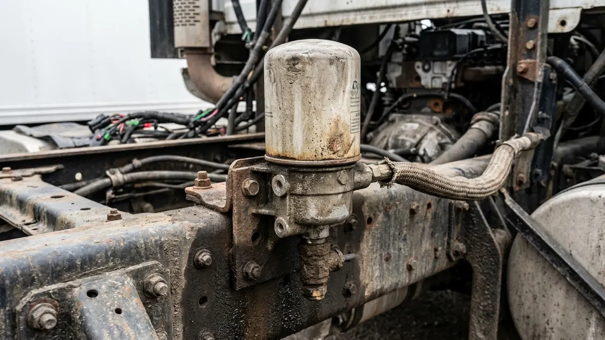
The Bendix AD-9 is a single-cartridge desiccant air dryer that sits between the air compressor's discharge line and the first (supply) reservoir, stripping water vapour, oil aerosol and solid contaminants out of the air before they reach the tanks and control valves. It purges on the governor's unloader signal, the same signal that unloads the compressor at cut-out, and it back-flushes its desiccant bed with dry air held in a purge volume. Knowing its four working connections, its roughly 30-second regeneration window and what a rebuild kit actually contains covers most of what a technician needs to diagnose one.
Where the AD-9 sits in the air supply
Air leaves the compressor hot, wet and carrying a small amount of oil. The discharge line is deliberately long and uninsulated so that air cools on the way and much of the moisture condenses before it arrives. The AD-9 collects that condensate in its sump, then passes the remaining air upward through the desiccant bed, where the drying agent adsorbs the water vapour that is still in suspension. Dried air leaves through a single check valve at the delivery port and charges the supply reservoir, from which the service and parking circuits are fed.
Because the dryer is the last component before the tanks, it inherits everything that goes wrong upstream. A dryer that vents a fine oil mist at every purge is almost never a failed dryer - it is a compressor passing oil into a saturated desiccant bed. Confirm the state of the compressor before condemning the unit, or the replacement will foul just as fast.
AD-9 port layout
The AD-9 has a small, consistent set of connections. Thread sizes vary slightly between build variants and OE part numbers, so confirm against the Bendix service data sheet for the unit stamped on your dryer before ordering fittings.
| Connection | Typical size | Connects to | Function |
|---|---|---|---|
| Supply (inlet) | 1/2 in NPT | Compressor discharge line | Wet, hot air in; feeds the sump and desiccant bed |
| Delivery (outlet) | 1/2 in NPT | Supply (wet) reservoir | Dry air out through the integral single check valve |
| Control | 1/4 in NPT | Governor unloader port | Opens the purge valve at cut-out, closes it at cut-in |
| Purge exhaust | Open to atmosphere | Purge valve housing, bottom of unit | Ejects contaminants and passes regeneration air |
| Safety valve | Boss in end cover | Atmosphere | Pressure relief if the delivery path becomes restricted |
| Heater and thermostat | 12 V or 24 V connector | Vehicle supply | Prevents the purge valve and exhaust freezing in cold weather |
The purge cycle and its timing
Purging is not on a timer inside the dryer. It is commanded by the air brake governor, which sends control air to both the compressor's unloader and the dryer's control port when the system reaches cut-out, usually somewhere in the 120-135 psi band on a healthy vehicle. When that signal arrives, the purge valve opens.
The first event is an audible blast lasting a fraction of a second, which ejects the liquid water, oil and sludge sitting in the sump. Immediately after, dry air stored in the purge volume flows back down through the desiccant bed in the reverse direction, lifting the adsorbed moisture off the drying agent and carrying it out of the exhaust. That regeneration flow runs for roughly thirty seconds until the purge volume is depleted.
The purge valve then remains open for the rest of the unloaded period. It closes when pressure falls to cut-in, typically around 100-110 psi, the governor exhausts the control line and the compressor loads again. On a vehicle with tight plumbing and low demand, that unloaded period can be several minutes; on a heavy-demand vocational unit it may be seconds, and a compressor that cycles constantly never gives the bed a full regeneration. See purge valve operation and service for the mechanical detail.
Turbo cut-off
Many AD-9 units carry a turbo cut-off valve. It exists for installations where the compressor's intake is fed from the engine's charge air rather than from a naturally aspirated source. On such an installation, when the compressor is unloaded and the dryer's purge valve is open, boosted intake air can travel through the unloaded compressor, down the discharge line and straight out of the dryer exhaust - taking engine oil with it and bleeding boost.
The turbo cut-off valve seals the inlet passage during the purge event so that path is closed. If it fails open, the symptoms are a dryer that exhausts continuously under load, an oily exhaust and a driver complaint about power. If it fails closed or sticks, the compressor cannot deliver into the dryer and the system will not build.
Heater, thermostat and safety valve
The end cover carries a thermostatically switched heating element in 12 V or 24 V form. It energises in cold ambient temperatures and keeps the purge valve and exhaust from icing shut. A dryer that works all summer and then refuses to purge below freezing is a heater circuit fault until proven otherwise: check the connector, the ground and the element resistance rather than replacing the dryer.
The safety valve is a mechanical relief device threaded into the end cover. If it vents, the dryer is being asked to hold pressure it cannot pass - typically a blocked desiccant cartridge, a seized check valve or a delivery-side restriction. Treat a venting safety valve as a diagnostic signal, not as a defective valve.
What is in an AD-9 rebuild kit
Kits are sold by function rather than as one large overhaul package, and the spin-on desiccant cartridge is always a separate item. Typical kit content is:
- Purge valve kit - purge valve assembly or housing, exhaust diaphragm, O-rings, springs and fasteners.
- Check valve kit - the single delivery check valve and its seals, which stop tank air flowing back into the dryer during purge.
- Heater and thermostat kit - element, thermostat and connector seal.
- Safety valve - supplied as a complete assembly.
- Turbo cut-off kit - valve, piston and seals, where the unit is so equipped.
- End cover gasket and O-ring set - always renew when the cover is disturbed.
The desiccant cartridge itself is a wear item on its own schedule; see cartridge replacement for intervals and technique. Complete valve assemblies and repair components in OE-grade form, including air dryer valves and dryer repair components, are available where a full unit change is not warranted. Torque every fastener to the manufacturer's published figures - the end cover is a pressure joint.
AD-9 versus AD-IP
| Point of difference | AD-9 | AD-IP |
|---|---|---|
| Purge volume location | Within the dryer housing | Integrated into the replaceable cartridge |
| Cartridge | Desiccant only, compact spin-on | Desiccant plus purge chamber, physically larger |
| Service effect | Purge volume stays with the vehicle for the dryer's life | Purge volume is renewed at every cartridge change |
| Body-level service | Purge valve, check valve, heater, safety valve serviceable | Comparable body-level service items |
| Interchange | Not a drop-in swap - bracketry, overall height and port orientation differ. Verify fitment and clearance before ordering. | |
Neither is inherently superior. The AD-9 is the widely stocked, well-understood baseline; the integral-purge design suits applications where a fresh purge volume at every service interval is preferred. Whatever is fitted, the governor setting, the length and routing of the discharge line and the health of the compressor determine dryer life far more than the model badge does.
Diagnosing a suspect AD-9
- No purge at cut-out - check for control air arriving at the control port first; a dead control line points at the governor or the line, not the dryer.
- Continuous exhaust while charging - purge valve held open, damaged exhaust diaphragm, or a failed turbo cut-off.
- Water in the reservoirs - saturated or oil-fouled desiccant, short unloaded periods, or a leaking check valve allowing wet air to reach the tanks.
- System will not build to cut-out - restricted cartridge, seized check valve or carbon-blocked discharge line; if the system also drops toward the low-air warning around 60 psi, treat it as a supply fault and work upstream.
Always drain the reservoirs and inspect what comes out before condemning the dryer. Clear water indicates a dryer or duty-cycle problem; a grey oil emulsion points at the compressor and means the whole supply side needs attention before a new dryer is fitted.
Source (VADEN Original): Air Dryer Cartridge and Moisture Management: Selection, Service Life and Winter Conditions
Need the part, not just the answer?
OE-grade air brake compressors and repair kits, manufactured and tested to commercial-vehicle standards.
Shop VADEN partsPublished by VADEN Original. Product links point to the manufacturer’s official catalogue. Specifications are general — always confirm figures against your vehicle’s service manual.