 airbrakecompressor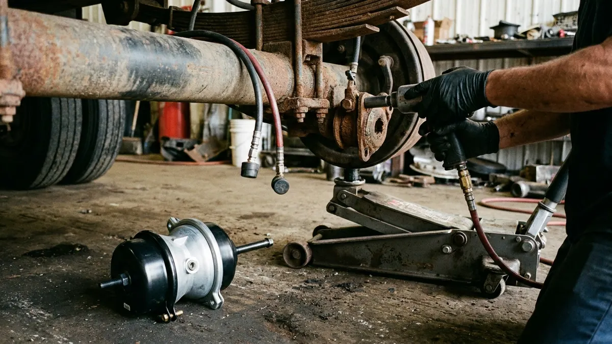
Changing a brake chamber is a straightforward job for a competent tech, but it is unforgiving if you rush the safety steps. The core sequence is this: cage the spring brake, drain the air system to zero, disconnect the air lines and pushrod clevis, unbolt the old chamber, bolt in the correct replacement, set the pushrod length and slack adjuster, then test for leaks and proper stroke. The single most dangerous mistake is opening a chamber that still has spring or air force loaded into it—so the caging and depressurizing steps below are non-negotiable.
This guide covers a standard S-cam foundation brake with a combination spring brake chamber (the common 30/30 type on drive and trailer axles). Front-axle service-only chambers are simpler because there is no power spring, but the air-side steps are the same.
Before You Start: Tools and Safety
Air brakes are pneumatic, not hydraulic, and the parking/spring section stores tremendous mechanical energy. A caged spring is your first line of defense; a fully drained system is your second. Never rely on wheel chocks alone.
- Chock the wheels front and rear so the vehicle cannot roll once parking brakes are released.
- Basic hand tools plus the caging tool (release stud) that ships with the chamber, and a breaker bar for the mounting nuts.
- Replacement chamber of the correct type number and pushrod length—confirm the stamping on the old unit (for example "3030" means a Type 30 service side and Type 30 spring side).
- Thread sealant or fresh push-to-connect fittings, and a torque wrench for the mounting and clamp band nuts.
Depressurize and Cage the Spring
With the engine off, pump the foot brake valve repeatedly to bleed the tanks, then open the tank drain cocks until the gauges read 0 psi. On a combination chamber, insert the release stud into the spring-side port, seat it, and turn the nut to mechanically cage (compress) the power spring. When it is caged, the parking force is locked out and the chamber is safe to remove. If you skip caging, the spring can launch the head assembly with lethal force.
Step-by-Step: Removing the Old Chamber
- Confirm zero pressure. Double-check every gauge reads 0 psi and the spring is fully caged before loosening anything.
- Mark and disconnect the air lines. Note which line feeds the service port and which feeds the spring/park port—tag them. Disconnect both and let any residual air escape.
- Free the pushrod. Remove the cotter pin and clevis pin connecting the pushrod to the slack adjuster. Measure and record the exposed pushrod length so you can set the new one identically.
- Unbolt the chamber. Remove the two mounting nuts holding the chamber to the bracket. Support the unit—these are heavy—and slide it off the studs.
- Inspect the mount and cam. Check the bracket, camshaft seal, and bushings for wear or corrosion while you have access. A weeping cam seal is worth fixing now.
Installing the Replacement Chamber
Install the new chamber with the drain hole (weep hole) pointing down so condensation and road spray drain out rather than pooling inside. Slide it onto the mounting studs and torque the nuts to the manufacturer's spec. Keep the spring caged until the unit is bolted down and the pushrod is connected.
Set the pushrod so its length and clevis position match what you recorded on the old unit, then install the clevis pin and a new cotter pin. Reconnect the air lines to the correct ports—reversing the service and spring lines will cause the brake to malfunction. Quality replacement chambers and related pneumatic components are available through VADEN's brake system parts range, where type numbers and stroke lengths are cataloged by application.
Uncage and Adjust
Once everything is bolted and connected, back out the caging stud to release the spring, then stow the stud in its holder on the chamber (never leave it loose). Charge the system by running the engine until the governor cuts out around 120–135 psi. Now adjust the slack adjuster to spec and verify free stroke and applied stroke are within legal limits.
Brake Chamber Type Reference
Chambers are sized by an effective-area number, and combination units carry two numbers—service side and spring side. Always match the original.
| Type number | Typical application | Notes |
|---|---|---|
| Type 24 | Service-only front axle | No spring; steer axle service brake |
| Type 30 | Service-only, some trailers | Common single-diaphragm size |
| Type 24/24 | Combination, lighter drive/trailer | Service + park spring |
| Type 30/30 | Combination, most drive & trailer axles | Most common on-highway size |
Testing After Installation
Do not return the vehicle to service until it passes a full check. Build the system to a fully charged pressure of roughly 120 psi, then:
- Static leak check: Shut the engine off, release the brakes, and watch the gauge. Soap the new chamber ports and clamp band—no bubbles, no measurable pressure drop beyond the allowable rate.
- Applied leak check: Hold the foot brake fully applied and watch for excess pressure loss and any hissing at the chamber diaphragm seam.
- Park and release: Pull the parking valve—the spring brake should apply firmly. Push it in—the chamber should release fully with no drag.
- Stroke check: Have a helper apply the brake and measure pushrod travel. Excessive stroke means the slack adjuster still needs work or the chamber size is wrong.
If the new chamber will not build or hold, or the whole system bleeds down, the chamber may not be the only issue—walk through air brake system pressure loss diagnostics before condemning the part. When one chamber has failed from age or corrosion, inspect its axle mate closely; replacing chambers in pairs keeps braking balanced side to side and saves a second trip under the truck.
Bottom line: the mechanical steps are easy—the discipline is in caging the spring and draining to zero every single time. A chamber under load has no give, and it does not warn you before it lets go.
Source (VADEN Original): Brake Chamber Types and Sizes: Choosing T, DD and Spring Chambers
Need the part, not just the answer?
OE-grade air brake compressors and repair kits, manufactured and tested to commercial-vehicle standards.
Shop VADEN partsPublished by VADEN Original. Product links point to the manufacturer’s official catalogue. Specifications are general — always confirm figures against your vehicle’s service manual.