 airbrakecompressor
Brake adjustment limits are the maximum applied pushrod stroke allowed for a given air brake chamber. Measure with the engine off, reservoir pressure between 90 and 100 psi, the parking brakes released and a full brake application held: if the pushrod travels to or past the limit for that chamber, the brake is out of adjustment and counts as a defective brake at roadside. For the most common chamber on the road — a standard-stroke Type 30 clamp chamber — that limit is 2 inches. A long-stroke Type 30 rated at 3.0 inches maximum stroke is allowed 2-1/2 inches.
Why applied stroke is the number that matters
An air brake chamber makes force pneumatically: air pressure pushes a diaphragm against a return spring, and the pushrod moves the slack adjuster, which twists the S-cam and spreads the shoes. The further the pushrod has to travel, the less force reaches the foundation brake and the more air each application consumes. A brake sitting at its limit still stops the truck on a dry, level road, but it runs short of usable stroke when the drums heat up and expand on a long grade, and it recovers slowly during repeated applications.
Two things set the limit: the chamber's design family (clamp, bolt, rotochamber or DD3) and its size number. The size number alone is not enough. A standard-stroke Type 30 and a long-stroke Type 30 carry different limits, and confusing the two is the most common mistake made in the yard.
Standard-stroke clamp-type chambers
These are the traditional chambers found on older tractors, trailers and vocational equipment. Outside diameter is the quickest way to confirm the size when the tag is unreadable.
| Chamber type | Approx. outside diameter | Readjustment limit (applied stroke) |
|---|---|---|
| Type 6 | 4-1/2 in | 1-1/4 in |
| Type 9 | 5-1/4 in | 1-3/8 in |
| Type 12 | 5-11/16 in | 1-3/8 in |
| Type 16 | 6-3/8 in | 1-3/4 in |
| Type 20 | 6-25/32 in | 1-3/4 in |
| Type 24 | 7-7/32 in | 1-3/4 in |
| Type 30 | 8-3/32 in | 2 in |
| Type 36 | 9 in | 2-1/4 in |
Long-stroke clamp-type chambers
Long-stroke chambers carry extra reserve travel and are standard on most late-model equipment. They are identified by a square-cut air inlet port boss, a trapezoidal identification tag and the rated maximum stroke — 2.5 or 3.0 — marked on the tag or clamp band. Note that a 2.5-rated long-stroke Type 30 gets the same 2-inch limit as a standard Type 30; only the 3.0-rated units gain travel.
| Chamber type | Rated maximum stroke | Readjustment limit (applied stroke) |
|---|---|---|
| Type 16 | 2.5 in | 2 in |
| Type 20 | 2.5 in | 2 in |
| Type 24 | 2.5 in | 2 in |
| Type 24 | 3.0 in | 2-1/2 in |
| Type 30 | 2.5 in | 2 in |
| Type 30 | 3.0 in | 2-1/2 in |
If you cannot positively identify the chamber, apply the shorter standard-stroke limit. Assuming long stroke on a chamber that turns out to be standard is how a truck ends up parked at a scale.
Bolt-type, rotochamber and DD3 limits
Older and specialty equipment still runs these families. Bolt-type chambers are lettered rather than numbered, and a rotochamber is noticeably narrower than a clamp chamber of the same rating.
| Family and type | Approx. outside diameter | Readjustment limit (applied stroke) |
|---|---|---|
| Bolt type A | 6-15/16 in | 1-3/8 in |
| Bolt type B | 9-3/16 in | 1-3/4 in |
| Bolt type C | 8-1/16 in | 1-3/4 in |
| Bolt type D | 5-1/4 in | 1-1/4 in |
| Bolt type E | 6-3/16 in | 1-3/8 in |
| Bolt type F | 11 in | 2-1/4 in |
| Bolt type G | 9-7/8 in | 2 in |
| Rotochamber 9 | 4-9/32 in | 1-1/2 in |
| Rotochamber 12 | 4-13/16 in | 1-1/2 in |
| Rotochamber 16 | 5-13/32 in | 2 in |
| Rotochamber 20 | 5-15/16 in | 2 in |
| Rotochamber 24 | 6-13/32 in | 2 in |
| Rotochamber 30 | 7-1/16 in | 2-1/4 in |
| Rotochamber 36 | 7-5/8 in | 2-3/4 in |
| Rotochamber 50 | 8-7/8 in | 3 in |
| DD3 Type 30 | 8-1/8 in | 2-1/4 in |
| DD3 Type 36 | 9 in | 2-3/4 in |
How to measure applied pushrod stroke
- Park on level ground and chock the wheels. Run the engine until the governor cuts out — on a healthy system that falls somewhere in the 120 to 135 psi range, with a fully charged system sitting around 120 psi — then shut it down.
- Fan the service brakes down until the gauges read between 90 and 100 psi. Stay in that window; the low-air warning normally activates around 60 psi and the spring brakes begin to apply below it.
- Release the parking brake control so the spring brakes are fully released and held off by air.
- With the brakes released, mark the pushrod where it leaves the chamber, using chalk or a marker.
- Have a helper make and hold a full application on the treadle valve.
- Measure from the chamber face to the mark. That distance is the applied stroke. Compare it with the chart for that exact chamber, and repeat at every wheel end.
Stroke measured with the wheels off the ground and a pry bar on the slack adjuster tells you about free play and lining clearance. It is a different number from applied stroke at 90 to 100 psi, and the two should never be checked against the same limit.
When one brake out of adjustment puts a truck out of service
Reaching the readjustment limit makes one brake defective; it does not automatically park the vehicle. Under the North American out-of-service criteria, a vehicle or combination is placed out of service when defective brakes reach 20 percent or more of the service brakes on the unit. On a five-axle tractor-trailer with ten service brakes, two brakes at or past their limit is enough. Steering-axle brakes and passenger-carrying vehicles are judged more strictly, and a defect found on a steering axle carries extra weight during a roadside brake inspection.
What to do when a brake is over the limit
Air-braked vehicles built since late 1994 use automatic slack adjusters. An automatic slack that is out of adjustment is reporting a fault, not asking to be cranked back in. Manual readjustment hides the real cause — a seized adjuster, worn clevis or pin, a dry or binding camshaft, worn linings, a cracked or oversize drum, or a slack arm installed at the wrong angle — and the stroke drifts back out within days. Diagnose the mechanism, replace what is worn, then verify stroke at every wheel end. See our slack adjuster adjustment procedure and the background on how slack adjusters work for the full sequence.
While you are under there, check the supporting items: chamber diaphragms for leaks, clevis pin wear, pushrod alignment and angle at the slack, and whether one chamber has been swapped for a different type than its mate on the same axle. Mismatched chambers side to side produce uneven torque and a pull under braking.
Air disc brakes do not use a stroke chart
Pneumatic disc brakes run on the same air supply but use a different actuator. The adjuster is internal and self-setting, so condition is judged by running clearance between pad and rotor plus remaining pad and rotor thickness against the manufacturer's specification. Never apply drum-brake stroke limits to a disc axle.
The figures above are the widely used North American inspection limits. Chamber suppliers and vehicle manufacturers publish tighter service values in some applications, and the current service manual for your specific chassis is always the governing document.
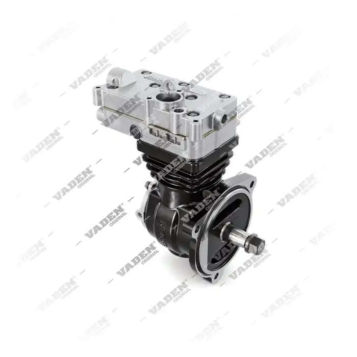
Need the part, not just the answer?
OE-grade air brake compressors and repair kits, manufactured and tested to commercial-vehicle standards.
Shop VADEN partsPublished by VADEN Original. Product links point to the manufacturer’s official catalogue. Specifications are general — always confirm figures against your vehicle’s service manual.