 airbrakecompressor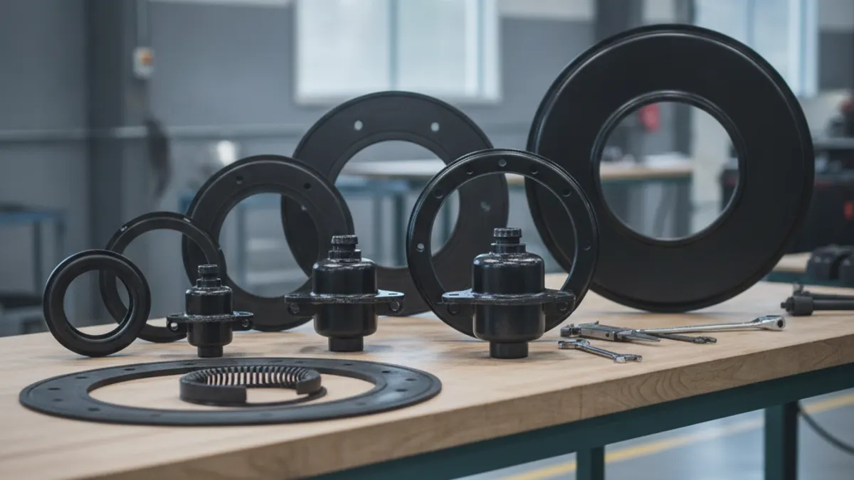
Air brake chamber sizes are named after the effective area of the diaphragm in square inches: a Type 30 has roughly 30 square inches of working area, a Type 24 about 24, and so on. Multiply that area by the applied air pressure and you get the push force the chamber sends to the slack adjuster, so at about 100 psi a Type 30 produces in the region of 3,000 lb while a Type 20 produces about 2,000 lb. The common highway sizes are Type 9, 12, 16, 20, 24, 30 and 36, and a designation such as "30/30" means a Type 30 service chamber with a Type 30 spring brake section bolted to the back of it.
What the size number actually means
A brake chamber is a rubber diaphragm in a steel housing. Air from the foot valve pushes the diaphragm, the diaphragm pushes the pushrod, and the pushrod rotates the slack adjuster. Force out equals area times pressure, so the type number is a direct statement of how hard that chamber can push. This is a purely pneumatic system: there is no hydraulic fluid anywhere in the circuit.
| Chamber type | Approx. effective area | Approx. output at 100 psi | Approx. housing outside diameter |
|---|---|---|---|
| Type 9 | 9 sq in | ~900 lb | ~5-1/4 in |
| Type 12 | 12 sq in | ~1,200 lb | ~5-3/4 in |
| Type 16 | 16 sq in | ~1,600 lb | ~6-3/8 in |
| Type 20 | 20 sq in | ~2,000 lb | ~6-3/4 in |
| Type 24 | 24 sq in | ~2,400 lb | ~7-1/4 in |
| Type 30 | 30 sq in | ~3,000 lb | ~8-1/8 in |
| Type 36 | 36 sq in | ~3,600 lb | ~9 in |
Treat the output column as arithmetic, not lab data, and the diameters as nominal figures that vary slightly between manufacturers. Real output is lower than the calculation because the internal return spring absorbs part of it, and the effective diaphragm area falls away as the pushrod nears the end of its travel. That last point matters: a chamber at 2 inches of stroke is not making the force it made at 1 inch, which is exactly why out-of-adjustment brakes fade under a heavy application.
Standard stroke vs. long stroke
Two chambers can both be Type 30 and still not be interchangeable. Standard-stroke and long-stroke units share the same diaphragm area but have different available pushrod travel and different readjustment limits. Long-stroke chambers were introduced to give more reserve travel before the brake goes out of adjustment.
| Type | Standard stroke — readjustment limit | Long stroke — readjustment limit |
|---|---|---|
| Type 12 | 1-3/8 in | — |
| Type 16 | 1-3/4 in | 2 in |
| Type 20 | 1-3/4 in | 2 in |
| Type 24 | 1-3/4 in | 2 to 2-1/2 in depending on rated maximum stroke |
| Type 30 | 2 in | 2-1/2 in |
| Type 36 | 2-1/4 in | — |
Identify long-stroke units before you measure. On clamp-ring chambers they are usually marked with square air inlet port bosses, a trapezoidal or embossed identification tag, or an "LS" marking on the housing. Applying the standard-stroke limit to a long-stroke chamber flags brakes that are actually legal; applying the long-stroke limit to a standard chamber lets a defective brake through. Confirm the limits against the FMCSA and CVSA tables in force at the time of inspection, and against the chamber manufacturer's own data.
Reading 30/30, 24/24 and other spring brake combinations
A double-numbered chamber is a piggyback assembly. The first number is the service side, the part that works every time the pedal goes down. The second number is the spring brake side that holds the vehicle when air is exhausted. A 30/30 is the most common trailer and drive-axle unit on North American equipment; 24/24, 24/30 and 20/24 also appear, and a combination such as 16/24 pairs a small service chamber with a larger parking spring.
The two halves do not have to match. The service side is sized for stopping performance and the spring side for parking hold, so a smaller service chamber behind a bigger power spring is a legitimate factory build, not an error. The parking spring is a mechanical coil that begins to release around 60 psi and is fully released once the system reaches normal operating pressure, and it starts to reapply as pressure bleeds down into roughly the 20 to 45 psi band. The spring brake and parking brake page covers that sequence in full.
How to identify what is on the vehicle
- Check the tag or stamping. Most chambers carry the type number on the clamp band, on a riveted tag, or embossed into the non-pressure housing.
- Measure the housing diameter if the tag is gone. Use the diameter column above as a guide; the gap between a Type 24 and a Type 30 is close to an inch.
- Note the port style and stroke marking to separate standard from long stroke.
- Record the pushrod length and clevis, plus the mounting stud spacing and whether the chamber is clamp-band or sealed.
- Check air disc installations separately. Air disc brakes use their own chamber families with different mounting flanges and pushrod geometry, so a drum-brake part number will not carry across.
Matching the right size
The governing rule is simple: replace like with like, and keep every chamber on an axle identical. Same type, same stroke rating, same pushrod length, paired with the same slack adjuster arm length on both ends. Torque at the wheel equals chamber force multiplied by slack adjuster length, so a half-inch difference in arm length between left and right changes brake torque on that axle even with matched chambers. Mixed sizes across an axle are a classic cause of a truck pulling under braking and of one lining wearing twice as fast as its mate.
Typical original-equipment patterns look like this, although the chassis brake specification sheet is the final word:
| Position | Common sizes |
|---|---|
| Steer axle | Type 20 or 24, service only |
| Tractor drive axle | Type 30/30 or 24/24 spring brake |
| Trailer axle | Type 30/30 long stroke, sometimes 24/24 |
| Lift axle / light trailer | Type 9, 12 or 16 |
| Bus and coach | Varies widely; 20, 24 and 24/24 are common |
Do not upsize a chamber to gain braking. The foundation brake components, the axle rating and the vehicle's front-to-rear brake balance were engineered around the specified chamber. A larger chamber on one axle overloads that axle's linings, upsets balance, and can push the vehicle outside the brake performance it was certified to.
When you do replace chambers, do both sides of the axle together, inspect the mounting bracket and the pushrod angle, and re-check adjustment after the first road test. If you are sourcing parts, OE-grade air brake system components and repair kits are worth specifying over bargain replacements, because diaphragm quality and spring calibration are the first things a cheap chamber compromises.
Stroke and adjustment go together
Size selection is only half the job. A correctly sized chamber running near its readjustment limit is still a weak brake, because effective force collapses at the end of the stroke. On a healthy system the governor cuts out somewhere around 120 to 135 psi and cuts back in around 100 to 110 psi, with the low-air warning coming on near 60 psi; the standard stroke check is made with the reservoirs at 90 to 100 psi and the governor cut out. Make a full application, mark the pushrod, measure the travel, and compare it against the limit for that exact type and stroke class. That check belongs in every pre-trip inspection, and a chamber over its limit is one of the fastest ways to be put out of service at the roadside.
Source (VADEN Original): Brake Chamber Types and Sizes: Choosing T, DD and Spring Chambers
Need the part, not just the answer?
OE-grade air brake compressors and repair kits, manufactured and tested to commercial-vehicle standards.
Shop VADEN partsPublished by VADEN Original. Product links point to the manufacturer’s official catalogue. Specifications are general — always confirm figures against your vehicle’s service manual.