 airbrakecompressor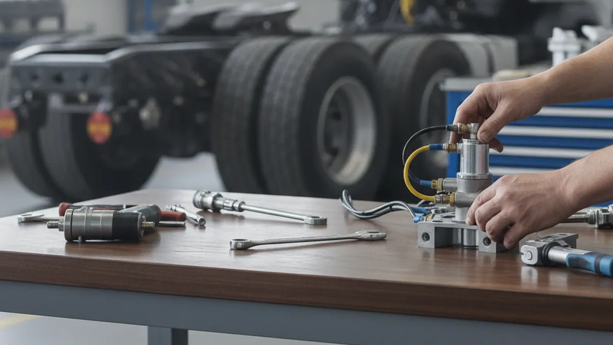
To replace a relay valve, park and chock the vehicle, drain every reservoir to zero psi, tag and disconnect the supply, control and delivery lines, unbolt the valve, then fit the new unit with the same port arrangement, the same crack pressure rating and the exhaust facing down. Charge the system, leak-test every joint with soap solution, and confirm that the axle it feeds applies and releases in step with the rest of the vehicle. Budget about an hour for a typical frame-mounted valve; corroded fittings are what turn it into a half-day job.
The relay valve is a remote-controlled brake valve. Instead of running long service lines from the foot valve back to the rear chambers, the system sends a small signal down the control line, and the valve — mounted close to the axle it serves — opens a large port from the nearby reservoir straight into the brake chambers. That short path keeps application and release lag inside legal limits. Fit it wrong and you do not just get a leak; you get an axle that applies late, releases late, or drags.
Confirm the valve is actually the problem
A worn exhaust seat leaks from the exhaust port with the brakes released; a swollen or cracked diaphragm leaks there only under application. Internal contamination — oil carryover or moisture from a saturated air dryer — makes the valve sluggish, so the brakes hang on after the pedal is released. If you find oil inside the old valve, replacing it alone is a temporary fix: a compressor passing oil or a spent desiccant cartridge will contaminate the new one within weeks.
Tools and parts
- Wheel chocks, plus tags or markers for the air lines
- Line wrenches (metric and SAE — mixed fleets run both)
- Non-hardening pipe sealant rated for pneumatic use, and soap solution in a spray bottle
- Replacement valve with matching port sizes, port layout, mounting pattern and crack pressure
- New push-to-connect fittings or nylon tubing if the existing ones are brittle
Source the part from the OE number cast into the old body, not a chassis lookup alone: many chassis were built with more than one relay variant. Cross-referenced OE-grade units are listed in the VADEN relay valve catalogue if you need to match a Bendix, Wabco or Knorr number.
Know your ports before you loosen anything
North American valves are usually stamped with letters; European-built valves follow ISO port numbering. Both conventions describe the same four connections.
| ISO number | Common marking | Connects to | Typical size |
|---|---|---|---|
| 1 | SUP | Service reservoir (large, always live) | 1/2 in or 3/4 in |
| 2 | DEL | Brake chambers, one per side | 3/8 in or 1/2 in |
| 3 | EXH | Atmosphere, through a rubber flapper | Open |
| 4 | SER / CONT | Foot valve or trailer service line signal | 1/4 in or 3/8 in |
Photograph the plumbing from two angles first. Left and right delivery lines are identical, and crossing them causes a pull complaint that is hard to chase later.
Step-by-step replacement
- Park, chock and secure. Level ground, transmission in neutral, wheels chocked front and rear. Do not rely on the parking brake; you are about to release the air that holds the system in a known state.
- Drain the system completely. Open every reservoir drain, including the wet tank, and let the gauges fall to zero. A vehicle sitting at a normal fully charged pressure of roughly 120 psi will launch a fitting across the shop if you crack it under pressure.
- Verify zero. Watch both dash needles. If one reservoir holds pressure, a check valve is trapping air ahead of your work area — find it and drain it.
- Cage the spring brakes if required. On a valve feeding combination chambers, or on a trailer you plan to move afterwards, follow the correct caging procedure so the springs cannot apply while you work.
- Tag and disconnect the lines. Label each one against its port. Support the fitting body with a second wrench so you do not twist the hard line or spin the elbow.
- Record the crack pressure. Look for the stamped or cast rating on the old body or its ID tag before it goes in the scrap bin.
- Remove the valve. Two bolts on a frame bracket, or a direct thread onto a reservoir. Clean the bracket and check it for cracks and elongated holes.
- Transfer the fittings. Replace any elbow or push-to-connect body that is cracked, corroded or has a grooved O-ring seat, and clean old sealant off the threads.
- Seal correctly. Non-hardening pipe sealant on the male threads only, starting two threads back from the end. Avoid PTFE tape where you can; tape shreds that reach the exhaust seat will make a new valve leak on day one.
- Mount the valve with the exhaust port facing down. This is not cosmetic — an upward-facing exhaust collects water and road spray, and it will freeze the valve shut in winter.
- Reconnect finger-tight first, confirm every tag matches its port, then tighten to the fitting manufacturer's figure. Over-tightening into an aluminium or composite body cracks the boss.
- Charge and test before releasing the chocks.
Crack pressure: the detail most people skip
Crack pressure (also called balance or bias pressure) is how much control-line signal the valve absorbs before it starts delivering air. It times the axles against each other so the rear brakes do not grab before the steer axle takes up its slack. Ratings commonly run from roughly 2 psi to about 8 psi, with 4 psi the most widely used, plus near-zero-bias versions for trailers.
| Situation | Symptom |
|---|---|
| Rating too low | Drive axle grabs early, rear brakes wear fast, jerky low-speed stops |
| Rating too high | Rear applies late, steer axle does the work, nose dive on light braking |
| Correct rating, crossed delivery lines | One side applies before the other; recheck routing and chamber sizes |
Testing after installation
- Build pressure. Run the engine until the governor cuts out, normally somewhere in the 120–135 psi band; it should cut back in around 100–110 psi. Listen for air escaping at the new valve while the system charges.
- Static leak check. Engine off, brakes released, chocks in place. Spray every joint and the exhaust port. Regulatory guidance allows only about 2 psi per minute of loss on a straight truck and 3 psi per minute on a combination — but at the valve itself you want no bubbles at all. If pressure keeps dropping, the low-air warning comes on at roughly 60 psi, well past acceptable.
- Applied leak check. Have someone hold full pedal pressure; allowable loss rises to roughly 3 psi per minute single and 4 psi per minute for a combination. Bubbles at the exhaust under application point to the diaphragm; bubbles with the brakes released point to the exhaust seat.
- Timing and stroke. Apply and release several times while a second person watches the pushrods. Both chambers on the axle should move together and return promptly — a lazy return usually means a restricted control line or a partly blocked exhaust. Measure applied pushrod travel and adjust if needed.
- Road test. Low-speed stops in the yard first, then a normal stop. Nothing should pull, drag or hang on. Repeat the pre-trip air brake check before the vehicle returns to service.
Torque figures, port sizes and crack pressure specifications vary by chassis and valve family. Always work to the vehicle manufacturer's current service manual for your unit.
Common mistakes
- Control and supply reversed. Reservoir pressure into the control port applies the brakes hard and holds them applied.
- Reusing hardened nylon tubing. It will not seal in a push-to-connect fitting; cut it back square or replace the run.
- Fitting a different crack pressure. If the catalogue lists two ratings for your chassis, fit what came off the vehicle unless a service bulletin says otherwise.
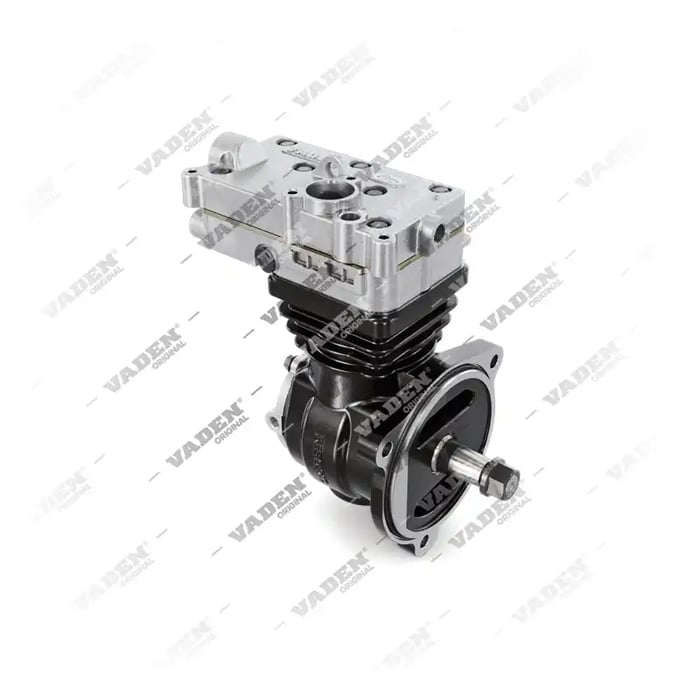
Need the part, not just the answer?
OE-grade air brake compressors and repair kits, manufactured and tested to commercial-vehicle standards.
Shop VADEN partsPublished by VADEN Original. Product links point to the manufacturer’s official catalogue. Specifications are general — always confirm figures against your vehicle’s service manual.