 airbrakecompressor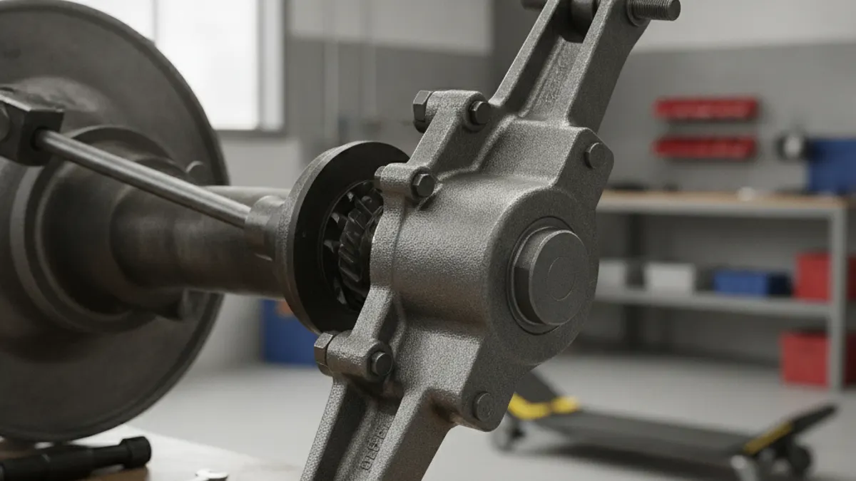
A Bendix slack adjuster is the lever that connects the brake chamber pushrod to the S-cam shaft on an air (pneumatic) brake, and on modern trucks it is almost always an automatic slack adjuster (ASA) that takes up lining-to-drum clearance by itself as the shoes wear. To fit one correctly, three things must match: the internal spline count of the camshaft, the effective arm length (cam bore center to clevis pin center), and the installation angle specified on the Bendix drawing for that axle position. Get any of those wrong and the brake will run long stroke no matter how often you adjust it.
What the automatic slack adjuster actually does
On an S-cam brake the chamber pushrod pushes the slack adjuster arm, the arm rotates the camshaft, and the cam spreads the shoes against the drum. As lining wears, the shoes travel further, so pushrod stroke grows. An ASA senses that extra travel and rotates its internal worm a few degrees to claw the clearance back, keeping applied stroke inside the readjustment limit.
There are two sensing philosophies in service. Stroke-sensing units measure how far the arm swings and adjust when the swing exceeds a set threshold. Clearance-sensing units act on the free-play portion of the stroke only. You cannot tell which you have from appearance alone, so pull the part number off the housing and read the matching Bendix service data sheet before you work on it.
One rule applies to every ASA: the manual adjusting nut is for installation and service, not routine adjustment. If you are cranking an ASA back into spec at every PM, the unit is worn, the clevis or anchor pin is sloppy, the cam bushings are shot, or the chamber is failing. Manual adjustment only hides it, and roadside inspectors treat an out-of-stroke automatic adjuster as a defective brake rather than one that simply needs adjusting.
Identifying a Bendix slack adjuster
Start at the housing. Bendix castings carry a part number and usually a date code, and on many units the spline count and arm length are stamped or cast in as well. If the number is unreadable, identify by measurement:
- Spline count — count the internal teeth in the bore, or count the teeth on the camshaft end before the old unit comes off.
- Effective arm length — cam bore center to clevis pin hole center. On arms with two or three clevis holes, measure to the hole actually in use.
- Offset and hand — many adjusters are offset or handed left and right. Compare old and new side by side before fitting.
- Control arm style — a fixed link to a bracket, a splined collar, or an integral sensing pawl. This determines how the installation angle is set.
| Variable | Typical range | How to confirm |
|---|---|---|
| Internal spline count | 10, 24, 28 or 37 teeth are seen most often; other counts exist | Count teeth on the camshaft end or in the adjuster bore |
| Effective arm length | Roughly 5 to 7 in (about 127 to 178 mm) | Cam bore center to clevis pin center |
| Clevis thread | Matched to the chamber pushrod thread; several sizes in service | Reuse only if undamaged; replace with the adjuster where specified |
| Offset / hand | Straight, offset, left or right | Side-by-side comparison with the removed unit |
| Installation angle | Per the Bendix drawing for that axle and chamber position | Service data sheet — do not eyeball it |
Arm length is not a preference item. It sets the mechanical advantage between chamber output and cam torque, and it is engineered together with chamber size for that axle. Fitting a 6 in arm where a 5.5 in arm belongs changes brake balance and can put a steer axle out of proportion with the drives.
Installation angle: the step most people rush
With the brakes released, the pushrod and the slack adjuster arm should form an angle slightly greater than 90 degrees, so the geometry passes through 90 degrees during the working part of the stroke. That is where the arm delivers maximum torque to the cam. Set too far one way and you lose torque at full application; too far the other way and the unit can over-travel.
On adjusters with an external control arm or reference link, that link is what tells the unit where zero is. It must be anchored to the bracket point shown on the installation drawing and positioned at the specified angle before initial adjustment is set. A control arm hung on a convenient bolt instead of the specified point is the most common reason a new Bendix ASA appears not to adjust.
- Cage the spring brake, block the wheels, and drain system pressure at the axle you are working on.
- Inspect the camshaft splines, bushings and seals. Replace worn cam bushings now — no adjuster can compensate for camshaft slop.
- Slide the adjuster onto the cam, fit the washer and retaining ring, and check for the specified end play.
- Connect the clevis with a new pin and retainer, holding the specified angle.
- Anchor the control arm to the drawing position and torque the bracket hardware to the Bendix figure.
- Set initial adjustment with the manual hex until the shoes just contact the drum, then back off per the data sheet.
- Build the system to a fully charged reading of about 120 psi, cycle the brakes several times, then measure applied stroke and confirm it is inside the readjustment limit for that chamber type.
Backing an ASA off is not always a matter of turning the hex counter-clockwise. Some designs require disengaging a pawl first, and forcing the hex against the one-way clutch will chew the internal gearing. Check the sheet for that part number before putting a wrench on it. The wider slack adjuster fundamentals and the stroke limit chart are worth having open while you work.
Lubrication interval and grease selection
An automatic slack adjuster is a small gearbox exposed to road spray, heat and vibration. Bendix calls for greasing at every scheduled maintenance interval, which in practice means every PM, and more often for vocational and severe-duty work.
| Item | Practice |
|---|---|
| Interval | Every scheduled PM; shorten for off-road, refuse, transit and winter salt exposure |
| Grease type | Lithium-complex EP chassis grease, NLGI Grade 1 or 2, rated for the operating temperature range |
| Method | Pump until fresh grease purges past the seal or relief — that purge is the confirmation |
| Also grease | Camshaft bushings and anchor pins at the same visit |
| Avoid | Mixing incompatible thickeners, or substituting a low-temperature grease on a unit that sees high drum heat |
An adjuster that will not take grease is telling you the internal passage is packed with hardened lubricant or the seal has failed. Replace it rather than keep pumping.
When to replace rather than diagnose further
Replace the unit if the arm is cracked or impact damaged, if there is measurable free play between the arm and the cam splines, if the housing leaks grease continuously, or if applied stroke keeps growing after correct initial adjustment and a verified installation angle. Replace adjusters in axle pairs where practical so both wheel ends behave the same. Chambers, camshaft kits and related foundation parts sit alongside slack adjusters in an OE-grade air brake system parts range, and matching the whole set is cheaper than chasing one wheel end twice.
Remember that stroke is a system symptom. Before condemning the adjuster, confirm the governor is cutting out in the normal 120 to 135 psi band and cutting in again around 100 to 110 psi, that the system holds a fully charged reading near 120 psi, that the low-air warning is not tripping (it should activate around 60 psi), and that the chamber diaphragm is sound. A weak chamber or a low-pressure system produces long stroke that no adjuster can fix. If the procedure is new to you, work through the adjustment procedure step by step before touching an automatic unit in service. Spline count, arm length, angle and torque figures must always be verified against the Bendix service data for that specific part number.
Need the part, not just the answer?
OE-grade air brake compressors and repair kits, manufactured and tested to commercial-vehicle standards.
Shop VADEN partsPublished by VADEN Original. Product links point to the manufacturer’s official catalogue. Specifications are general — always confirm figures against your vehicle’s service manual.