 airbrakecompressor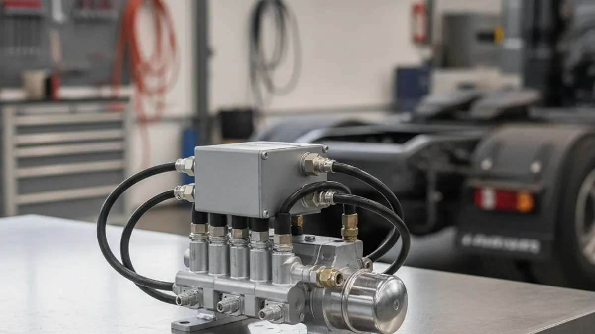
Trailer ABS is an electronic layer on top of the trailer's pneumatic service brakes. A wheel speed sensor at each monitored wheel end watches rotation, and when the electronic control unit sees a wheel about to lock during a stop, it commands a modulator valve to release and restore air at the brake chambers several times a second. The wheel keeps turning, the trailer keeps tracking behind the tractor instead of swinging out, and the tires keep gripping.
Two points are worth being clear about. ABS cannot apply the brakes; it only modulates pressure the driver has already commanded through the foot valve. And if the ABS drops offline, the trailer still has full normal braking. What you lose is the anti-lock function, not the brakes.
What is actually on the trailer
Wheel speed sensors and exciter rings
Each monitored wheel end carries a variable-reluctance sensor riding against a toothed exciter ring (tone ring) pressed onto the hub. As the ring turns, the sensor produces a small AC signal whose frequency tells the ECU how fast that wheel is turning. The sensor sits in a spring clamp bushing and is pushed fully in against the ring on installation; the running clearance establishes itself as the wheel end settles. A sensor that has walked back out of its bushing, or a ring with chipped or missing teeth, gives an intermittent fault that shows up only at certain speeds.
Modulator valve
The modulator is a solenoid-operated valve plumbed between the pressure source and the chambers it controls, and on many trailers it is combined with the relay valve in a single body. One solenoid blocks incoming pressure (hold), the other vents chamber pressure to atmosphere (release), and when the ECU stops commanding, pressure is restored. Rapid chuffing from the valve during an ABS stop is normal and is not a leak.
ECU and wiring
The ECU is usually mounted on the modulator or on a crossmember, and it handles diagnostics, the lamp driver and, on many units, roll stability logic. Everything else is harness: sensor extensions, power and ground, lamp circuits. On equipment that lives outdoors, harness and connector condition is the single biggest reliability factor.
Sensor and modulator configurations
Layouts are written as "S/M", meaning sensors over modulators. More of each buys finer control per wheel end and better diagnostics, at higher cost.
| Layout | Sensors | Modulators | Typical use |
|---|---|---|---|
| 2S/1M | 2 (one axle, both sides) | 1 | Base-spec single or tandem-axle van, converter dolly |
| 2S/2M | 2 | 2 (side-by-side control) | Trailers with split-side control |
| 4S/2M | 4 (both axles) | 2 | Common premium spec on tandems |
| 4S/3M or 6S/3M | 4-6 | 3 | Tridems, heavy haul, spread-axle flats |
The ABS power line and the lamps
Trailer ABS is fed from the tractor through the seven-way J560 connector. The auxiliary (center) pin, commonly the blue wire, carries constant power to the trailer ECU, with the white circuit as ground. Constant power matters: the ECU wakes up and runs its self-check the moment you plug in, rather than only when the brake pedal is pressed. Some older trailers were wired to take ABS power from the stop-lamp circuit, which is why they look dead until the driver steps on the brake.
There are two lamps to read:
- External trailer lamp. A yellow lamp on the left (roadside) of the trailer, positioned so the driver can see it in the mirror. It illuminates at power-up, then goes out after a couple of seconds if the system is healthy.
- In-cab trailer ABS telltale. The trailer ECU reports its status back to the tractor over the same power wire using a power line carrier signal, so the dash lamp mirrors the trailer's fault state without extra wiring.
A lamp that stays on after the self-check means an active fault. A lamp that never lights at all is also a fault, usually no power, a bad ground or a burned-out bulb, and it fails an inspection just the same. This is a separate circuit from the supply and service plumbing covered under the semi-trailer air brake system.
Diagnosing a trailer ABS fault
Work outside-in. The ECU is the last thing you condemn, not the first.
- Charge the system, then watch the power-up sequence. Plug in the seven-way, let the air build and watch both lamps. A healthy governor typically cuts out somewhere around 120-135 psi and cuts back in around 100-110 psi, so a fully charged trailer should sit near 120 psi before you test anything, and the low-air warning comes in around 60 psi. No lamp at all points at power or ground; steady-on points at an active fault.
- Check power and ground at the nosebox. Measure voltage on the auxiliary pin with the tractor key on and the brakes released, and check ground continuity on the white circuit. Pull the plug and inspect both halves for green corrosion, spread sockets and a loose strain relief.
- Pull the codes. Most trailer ECUs blink a fault code through the external lamp, and all of them read out through a diagnostic tool. Codes name the wheel end and the failure type: open, short, wrong signal, no signal.
- Test the sensor. Unplug it and read resistance across the pins against the manufacturer's figure, which for most units falls somewhere between several hundred and a few thousand ohms. Then set the meter to AC volts and spin the wheel by hand; you should see a small output. Check insulation resistance to ground as well.
- Inspect the wheel end. Pull the sensor, confirm it is clean and free in its bushing, and push it back in until it contacts the tone ring. Look for damaged, rusted or loose exciter rings and check bearing endplay, because excessive endplay lets the gap open under load and produces faults only when the trailer is loaded or cornering.
- Check the modulator. Solenoid coil resistance should match spec, and the valve should cycle audibly when the tool commands it. Oil or water blowing from the exhaust port points upstream, to air supply and drying, not to the ABS.
Frequent causes, ranked by how often you find them
| Symptom | Most likely cause |
|---|---|
| Lamp on with one trailer, off with another | Tractor-side auxiliary circuit dead, or corroded nosebox |
| Lamp on intermittently, clears on restart | Chafed sensor lead or loose sensor in its bushing |
| Fault only when loaded or turning | Wheel bearing endplay or a shifted exciter ring |
| Lamp never illuminates at all | Burned bulb, open ground, or no constant power |
| Fault right after a tire or hub change | Mismatched tire sizes, wrong tone ring tooth count, or sensor not seated |
Inspection and compliance
In the United States, air-braked trailers built on or after 1 March 1998 must have ABS, and an external malfunction lamp has been required on trailers built since 1 March 2001. Inspectors look for that lamp cycling correctly at power-up. An ABS malfunction is recordable and affects carrier safety scores; on its own it is usually not an out-of-service condition, but the brake defect behind it may well be, so check current inspection criteria rather than assuming. Add the lamp check to the plug-in step of your walkaround, and remember that ABS masks nothing: a wheel end out of adjustment still shows up in a brake check. For the tractor side and how the two ECUs coexist, see ABS on air brakes; if the fault turns out to be plumbing rather than electronics, start at the service trailer brake system.
Shop-floor rule of thumb: if the ABS lamp came on the same week you had a wheel end apart, the fault is at that wheel end until you prove otherwise.
Once sensor gap, wiring and ECU have all checked out, the modulator itself is the remaining suspect, and it is replaced as a sealed unit rather than stripped — ABS solenoid modulator valves are what you quote at that point.
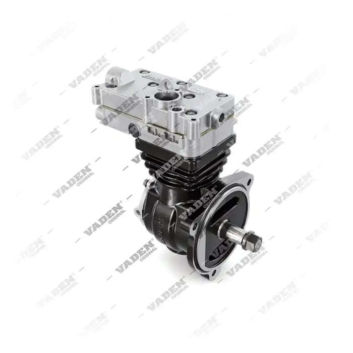
Need the part, not just the answer?
OE-grade air brake compressors and repair kits, manufactured and tested to commercial-vehicle standards.
Shop VADEN partsPublished by VADEN Original. Product links point to the manufacturer’s official catalogue. Specifications are general — always confirm figures against your vehicle’s service manual.