 airbrakecompressor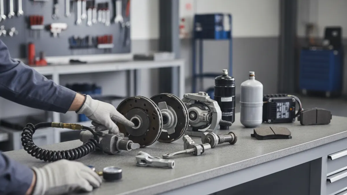
The seven-step air brake check is the sequence a CDL driver performs to prove the pneumatic brake system holds pressure, warns of low air, and applies the spring brakes when it should. In order, the seven steps are: check governor cut-in and cut-out, test the static leakage rate, test the applied leakage rate, test the low-air warning device, test the spring-brake (automatic application) point, test that the system rebuilds pressure, and test service brake operation. You perform it with the engine off for the leak-down portions and the wheels chocked, and you need to know the target psi for each step because an examiner can fail you for a wrong number just as fast as for a skipped step.
What follows is the walkthrough as a technician runs it in the yard, with the pass/fail figures that matter. If you want the wider testing context, the CDL air brake test guide covers the written and inspection portions around this procedure.
Before you start: charge and set up
Run the engine until the system is fully charged, typically to about 120 psi and no higher than governor cut-out. Chock the wheels, then shut the engine off for the leak-down steps and turn the key to the on or accessory position so the gauges and warning devices stay live. Everything below assumes a fully charged, air-tight starting point. If your system will not build to cut-out in the first place, stop and diagnose that first, because a compressor that will not build pressure invalidates the rest of the check.
The seven steps and their target figures
| Step | What you test | Pass figure |
|---|---|---|
| 1 | Governor cut-in and cut-out | Cut-in ~100-110 psi, cut-out ~120-135 psi |
| 2 | Static (parked) leakage rate | Under ~2 psi/min single, ~3 psi/min combination |
| 3 | Applied leakage rate | Under ~3 psi/min single, ~4 psi/min combination |
| 4 | Low-air warning device | On at or before ~60 psi |
| 5 | Spring-brake automatic application | Knobs pop out in ~20-45 psi range |
| 6 | Pressure rebuild (compressor) | 85-100 psi in ~45 seconds or less |
| 7 | Service brake check | No abnormal leak, no pull, firm hold |
Step 1 — Governor cut-in and cut-out
With the engine running and building air, watch the dash gauge. The governor should stop the compressor from pumping (cut-out) somewhere in the 120-135 psi band. Then fan the service brake down with repeated applications until the governor lets the compressor load again; that cut-in point should land around 100-110 psi. Wide, wandering, or reversed numbers point to a faulty governor or unloader. This confirms the system cycles within spec before you start leak testing.
Step 2 — Static leakage rate
Fully charge, shut the engine off, release the brakes (push both knobs in), and time the pressure drop for one minute without touching the pedal. For a straight truck or bus the drop should stay under about 2 psi in a minute; for a tractor-trailer or other combination, under about 3 psi. More than that means a leak in the reservoirs, lines, or fittings feeding the air tanks. This is the strictest, quietest test in the sequence, so let the gauge settle before you read it.
Step 3 — Applied leakage rate
Still engine-off and fully charged, apply and hold full pressure on the foot brake for one minute and again watch the drop. The applied limit is looser because you have opened the service circuit to the brake chambers: under about 3 psi for a single vehicle, under about 4 psi for a combination. Excess drop here points to a leaking service line, foot valve, relay valve, or brake chamber diaphragm rather than the reservoirs.
Step 4 — Low-air warning device
With the engine off, begin fanning air out of the system by pumping the brake pedal. The low-air warning — buzzer, light, or wig-wag — should activate at or before about 60 psi. This is the alarm that gives a driver time to stop safely before the spring brakes slam on, so it is a hard pass/fail. If it comes on late or not at all, the vehicle is unsafe regardless of how well everything else tested.
Step 5 — Spring-brake automatic application
Keep fanning the pressure down past the warning. As tank pressure falls into roughly the 20-45 psi range, the parking and tractor-protection knobs should pop out on their own and the spring brakes should apply mechanically. That automatic apply is the entire safety premise of an air system: lose air, lose motion. If the knobs do not pop in that band, suspect the tractor protection valve or the spring-brake control.
Step 6 — Pressure rebuild
Start the engine and let the compressor work with the brakes released. From a discharged state it should build from 85 to 100 psi in about 45 seconds or less on a typical single vehicle; combinations are allowed a bit longer. Slow rebuild, or a system that will not climb back to cut-out, is a sign of a weak or worn compressor and often shows up alongside other failing-compressor symptoms.
Step 7 — Service brake check
Fully charge, release the parking brake, roll forward at about 5 mph, and apply the foot brake firmly. The vehicle should stop straight with no pulling to one side, no delay, and no unusual noise. A pull or a soft pedal points to a mechanical foundation-brake problem — slack adjuster, chamber, or lining — not a pressure problem.
Why examiners weight each step
Steps 4 and 5 are the ones examiners rarely let slide, because the low-air warning and the spring-brake apply point are what keep a runaway from happening when air is lost. Steps 2 and 3 prove the system is tight enough to hold that air in the first place, and step 1 proves it recharges within spec. Treat any single failure as disqualifying: on a skills exam it ends the air-brake portion, and at a roadside inspection the same defects place the unit out of service.
Common mistakes that fail drivers
- Reading the gauge too soon. Pressure needs a moment to stabilize after you shut the engine off; read the one-minute drop from a settled needle.
- Confusing the two leak limits. Static and applied have different thresholds, and combinations get more allowance than single vehicles — mixing them up gets the wrong verdict.
- Skipping the warning-then-spring sequence. Steps 4 and 5 must be done in order as you fan pressure down; jumping straight to the spring brakes skips the warning test.
- Not chocking the wheels. The procedure runs with the parking brake cycled off at points, so chocks are mandatory.
Run the seven steps the same way every time and the numbers become second nature. If any step drifts out of the bands above, the fix is usually upstream in the charging or foundation hardware — start with how the air brake system works to trace which component owns the failure.
When a step fails, the psi at which it failed tells you which component owns it, and matching that governor, foot valve or chamber against the air brake system parts catalogue lets you order before the truck is booked back in.
Need the part, not just the answer?
OE-grade air brake compressors and repair kits, manufactured and tested to commercial-vehicle standards.
Shop VADEN partsPublished by VADEN Original. Product links point to the manufacturer’s official catalogue. Specifications are general — always confirm figures against your vehicle’s service manual.