 airbrakecompressor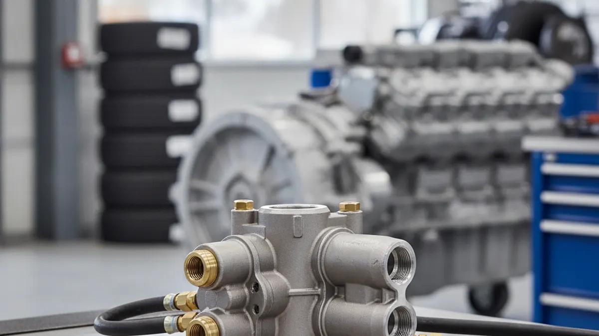
A multi-circuit protection valve (commonly a four-circuit protection valve, or MCPV) takes the single dried air supply leaving the air dryer and divides it into several independent brake and auxiliary circuits, each with its own protection element. Its job is safety: if a line, tank or fitting on one circuit fails, that element closes and holds the remaining circuits at pressure so the vehicle still has braking capability. It also enforces a charging priority, filling the service brake circuits before the parking, trailer and accessory circuits.
The valve is standard on European-design trucks, buses and coaches (MAN, Mercedes-Benz, Volvo, Scania, DAF, Iveco, Renault) and on many trailers and specialty chassis. North American tractors reach the same result with a supply reservoir, one-way check valves and individual pressure protection valves, but the principle is identical: this is a purely pneumatic safeguard, with no hydraulic circuit involved anywhere in the system.
What the multi-circuit protection valve actually does
Inside a single cast body are three, four or five independent valve elements, each a diaphragm or piston loaded by a calibrated spring. Air arrives at the common supply port and must overcome each spring before it can pass into that circuit. Three functions come out of that arrangement:
- Division. One supply becomes several circuits, each feeding its own reservoir.
- Isolation. If pressure in one circuit falls below that element's closing pressure, the element shuts and stops the intact circuits from draining into the failed one. This is what makes a dual air brake system genuinely redundant rather than just duplicated.
- Prioritisation. The service brake elements have the highest closing pressures, so during charge-up and during a partial failure the brakes get air before anything else.
Where it sits in the air system
Follow the air path: compressor to air dryer, dryer outlet to the multi-circuit protection valve supply port, then out of the valve to the individual reservoirs. On many modern chassis the valve is bolted directly to the dryer as part of an air processing unit. The governor still controls compressor cut-in and cut-out upstream, and the dryer still purges independently.
That order matters when you are diagnosing, because everything the protection valve delivers has already passed through the dryer. Oil or water found at the valve outlets points at a dryer or compressor problem, not at the valve.
Port numbering and circuit priority
Most European valves follow the ISO/DIN port numbering cast into the body. Actual assignments vary by chassis, so confirm against the vehicle plumbing diagram before you cap or swap a line.
| Port | Circuit | Typically feeds | Fill priority |
|---|---|---|---|
| 1 | Supply | Inlet from air dryer / compressor | — |
| 21 | Service brake circuit 1 | Rear axle service reservoir | First |
| 22 | Service brake circuit 2 | Front axle service reservoir | First |
| 23 | Parking / trailer circuit | Spring brake and trailer supply reservoir | Second |
| 24 | Auxiliary circuit | Air suspension, PTO, cab tilt, doors, horn, seat | Last |
| 25 | Second auxiliary (if fitted) | Bodybuilder / secondary accessories | Last |
Because ports 23 and 24 open last, it is normal for the parking brake to take longer to release than the service gauges take to rise, and for air suspension to come up last of all. On a healthy system the whole sequence completes within a few minutes of idling from empty.
Opening, closing and static pressures
Each element is defined by two numbers. The opening pressure is where the element first admits air to its circuit during charge-up. The closing pressure (sometimes split into static and dynamic closing pressure) is where the element shuts to protect the remaining circuits during a failure. Service circuits are always set with the highest closing pressures and auxiliary circuits with the lowest, so the accessories are sacrificed first.
Do not guess these values. They are model-specific, published in the OE service data, and on many valves stamped or labelled on the body. Work in the units the chassis was built to. A North American air brake system is typically fully charged around 120 psi, with governor cut-in near 100–110 psi, cut-out in the 120–135 psi range, and the low-air warning active around 60 psi. European heavy vehicles fitted with multi-circuit protection valves are calibrated in bar and generally run a higher reservoir pressure, broadly in the 8–12.5 bar region (roughly 115–180 psi) depending on chassis and circuit. Judging a bar-rated valve against psi figures from another market is a common way to chase a fault that is not there. In all cases the vehicle manufacturer's current service data is decisive.
Symptoms of a failing multi-circuit protection valve
| Symptom | What it usually means |
|---|---|
| One reservoir never reaches full pressure, the others do | That element is stuck partly closed, or its seat is contaminated |
| Parking brake will not release, or releases very late | Port 23 element not opening; verify supply pressure first |
| Air suspension slow or dead, brakes normal | Port 24 element sticking — often the first circuit to show wear |
| Audible leak at the valve body, compressor cycles constantly | Failed diaphragm or O-ring; see air brake system losing pressure |
| One circuit drains overnight, the others hold | Internal cross-leak or a check function that no longer seals |
| All circuits build slowly with a known-good compressor | Restricted supply port, or a dryer passing debris into the valve |
How to test a multi-circuit protection valve
- Chock the wheels and note the pressure in every reservoir before you start. Work with the engine off wherever the procedure allows.
- Drain all reservoirs, then charge the system and watch each circuit gauge. Confirm the service circuits rise first, parking next, auxiliaries last. A circuit that lags badly out of sequence is the suspect.
- Charge to full system pressure and shut down. Soap the valve body, each port and every fitting. Sustained bubbling at the body itself is an internal failure, not a fitting leak.
- Run the isolation test: with the system fully charged, open the drain on one circuit only and watch the remaining gauges. The intact circuits should stabilise and hold once the failed circuit drops below its closing pressure. If they keep falling with it, the valve is not protecting.
- Repeat for each circuit in turn, then recharge and verify the low-air warning and parking brake behave normally.
- For bench work, plumb regulated shop air to the supply port with a gauge on each outlet and compare measured opening and closing pressures against the OE specification for that part number.
Never cap or plug a protection valve port to "fix" a leaking circuit. That removes a designed redundancy and will put the vehicle out of service on inspection.
Repair or replace
Most modern multi-circuit protection valves are sealed, calibrated assemblies. A few designs accept a seal and diaphragm kit, but any unit with a corroded bore, a scored piston or a seat that will not hold after cleaning should be replaced rather than reworked — a valve that opens correctly but closes late is more dangerous than one that fails outright. Match by OE number and by circuit count and port layout, since three-, four- and five-circuit bodies share the same footprint on some chassis. Replacement units are listed in the VADEN multi-circuit protection valve catalogue by cross-reference number.
When you fit a new valve, blow the supply line clear first. Contamination from a failing air dryer cartridge or a compressor passing oil is the most common reason a replacement valve fails early, so correct the upstream cause before you close the hood. Recharge, run the isolation test on every circuit, and confirm the parking and trailer supply circuits release cleanly before the vehicle goes back into service.
Source (VADEN Original): Four-Circuit Protection Valve: Faults, Diagnosis & Replacement
Need the part, not just the answer?
OE-grade air brake compressors and repair kits, manufactured and tested to commercial-vehicle standards.
Shop VADEN partsPublished by VADEN Original. Product links point to the manufacturer’s official catalogue. Specifications are general — always confirm figures against your vehicle’s service manual.