 airbrakecompressor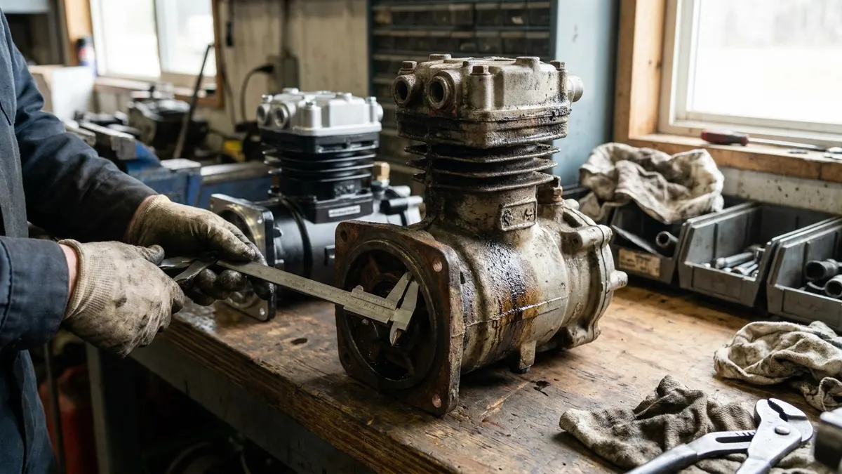
Truck air compressors are sized by displacement - the volume of air the pistons sweep per revolution - which North American catalogues publish as CFM (cubic feet per minute) at a stated compressor speed and European catalogues publish as litres per minute. A conventional line-haul tractor is usually well served by something in the 12-16 CFM class, while vocational trucks and city buses running air-operated bodies, doors and suspensions typically need 18-30 CFM or more. The target is not the biggest pump that will bolt on: it is a unit that keeps the system charged while spending most of its running time unloaded.
What a CFM rating actually measures
A published CFM figure is delivered air volume at a reference speed - commonly 1,250 rpm measured at the compressor, not at the crank. Because most gear-driven units turn at or slightly above engine speed, real output at highway rpm is higher than the catalogue number, and output at idle is considerably lower. That is why a marginal compressor announces itself in stop-and-go and PTO work long before it does on the interstate.
European suppliers state the same property as litres per minute at their own reference speed, so convert before deciding one unit is "bigger" than another. Cylinder count is a related but separate question: a large single-cylinder unit can out-flow a small twin, so read displacement rather than counting bores - see single vs twin cylinder air compressors for how the two compare on heat and sustained duty.
Output classes and their rough equivalents
| Class | Approx. CFM | Approx. l/min | Nominal cc per rev | Typical use |
|---|---|---|---|---|
| Light | 8-12 | 225-340 | 180-270 | Light air brake and air-over-hydraulic chassis, small buses |
| Standard | 12-16 | 340-450 | 270-360 | Line-haul and regional tractors |
| Heavy | 16-22 | 450-620 | 360-500 | Vocational, heavy haul, coach |
| Extra heavy | 25-35+ | 700-1000+ | 570-790 | Refuse, mixer, transit and articulated bus, air-hungry bodies |
The cc-per-revolution column is nominal, derived from the rated flow at the reference speed; use it only to compare units across catalogues that quote different units.
Matching output to the application
Braking is rarely the whole load. Every air-operated accessory on the chassis - axle shift, tailgate, body dump, seat, door, kneeling suspension - draws from the same reservoirs, and every one of them lengthens the time the compressor spends loaded.
| Application | Main air consumers | Suggested class | Sizing note |
|---|---|---|---|
| Line-haul tractor | Service brakes, air ride, seat, horn | 12-16 CFM | Low stop frequency; duty cycle stays low if the system is tight |
| Regional / P&D straight truck | Frequent applications, lift gate and door controls | 13-18 CFM | Stop count, not mileage, drives demand |
| Vocational (dump, mixer, refuse, plow) | Axle shift, tailgate, body air, PTO controls | 18-30 CFM | Body air can exceed brake demand; spec generously |
| Transit bus | Doors, kneeling, ramp, dozens of stops per hour | 20-35 CFM | Highest duty cycle in the fleet; dryer capacity must match |
| Coach | Doors, levelling, fewer stops | 16-25 CFM | Long runs at cruise help, but levelling valves bleed continuously |
| Multi-axle heavy haul | Large chamber count across many axles | 18-30 CFM | Reservoir volume matters as much as pump output |
Storage and output work together. FMVSS 121 requires total reservoir volume of at least twelve times the combined volume of the service brake chambers, so a vehicle with more axles or larger chambers needs both more storage and more pump to refill it after an application.
Duty cycle is the number that actually matters
Governor cut-out normally sits in the 120-135 psi band and cut-in in the 100-110 psi band, so the compressor loads every time pressure falls through cut-in and unloads again at cut-out. The fraction of running time spent loaded is the duty cycle, and the working target is under roughly 25%. Beyond that, discharge temperature climbs toward the commonly cited ceiling of about 400 F (roughly 200 C), where oil begins carbonising in the cylinder head and discharge line. The carbon restricts flow, which raises temperature further - a loop that ends in a failed compressor and a contaminated dryer. Before blaming capacity, confirm the governor is cutting out where it should; a unit that never unloads runs at 100% duty cycle regardless of how much CFM it makes.
What an undersized compressor does to the rest of the system
- Pressure hangs below cut-out under working load and the governor rarely unloads.
- The air dryer sees a near-continuous charge cycle, cannot regenerate the desiccant, and starts passing moisture downstream.
- Ring and cylinder temperatures rise, oil carryover increases, and oil shows up in the tanks and valve bodies.
- Carbon accumulates in the discharge line and the dryer inlet.
- Recovery is slow after a low-air event - the warning device trips around 60 psi and spring brakes apply somewhere in the 20-45 psi range, and getting back to a fully charged system near 120 psi takes far longer than it should.
If that is the behaviour you are chasing, prove it is capacity and not something cheaper first. A compressor that runs constantly is far more often a leaking system, a saturated dryer or a stuck unloader than a genuinely undersized pump.
No compressor is big enough to out-run a leaking system. Fix leakage first, then size for demand.
Why bigger is not automatically better
Extra displacement is not free. It adds parasitic load and fuel burn, raises torque through the drive gear and mounting, and pushes more oil vapour and moisture per minute into the air dryer. Stepping up output without stepping up dryer and purge capacity simply moves the failure downstream to the cartridge. A larger unit may also demand a higher oil feed rate and a water-cooled head where the outgoing one was air-cooled. Match the increase across the whole charging circuit, or leave the output where the OE put it.
Spec-sheet checklist before you order
- Rated displacement at the stated speed, compared against the OE figure for that engine rather than the truck model.
- Drive and mounting: splined or bolted drive gear, flange pattern and bolt circle, belt or clutch drive.
- Cooling: air-cooled versus water-cooled head, and coolant port location and thread.
- Lubrication: pressure-fed from the engine or self-lubricating, plus oil feed and drain port positions.
- Unloader arrangement: integral unloader in the head versus external governor plumbing, and signal line thread size.
- Port sizes and orientation for inlet, discharge and governor signal - a correct-CFM unit with the discharge facing the wrong way turns a parts swap into a fabrication job.
- Cross-reference by engine and OE number, since the same chassis is often built with two or three compressor options. Serious suppliers publish displacement next to the cross-reference; VADEN's OE-grade air brake compressor range, for example, lists output alongside Bendix, Wabco/ZF, Knorr-Bremse and truck-OEM numbers.
A quick check before you spend money
Run the build-up test: with the reservoirs drained and the engine at maximum governed speed, FMVSS 121 expects service pressure to climb from 85 to 100 psi in about 25 seconds. Then check static leakage with the engine off and the system charged - the standard limits are 2 psi per minute for a single vehicle and 3 psi per minute for a combination with the brakes released, and 3 and 4 psi per minute respectively with the brakes applied. A truck that fails build-up but passes leakage is genuinely short of pump. One that fails leakage will never hold pressure no matter what you bolt on.
Need the part, not just the answer?
OE-grade air brake compressors and repair kits, manufactured and tested to commercial-vehicle standards.
Shop VADEN partsPublished by VADEN Original. Product links point to the manufacturer’s official catalogue. Specifications are general — always confirm figures against your vehicle’s service manual.