 airbrakecompressor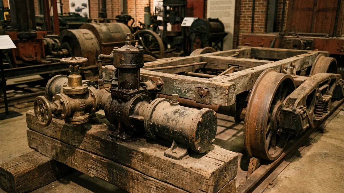
Railway air brakes and truck air brakes are both pneumatic systems built on the same fail-safe promise: lose the air, and the brakes come on by themselves. The mechanism is what differs. On a train, a drop in brake pipe pressure is the command that tells each car's control valve to dump its own stored reservoir air into the brake cylinder. On a truck, the service brakes work the opposite way — the treadle valve adds pressure to the brake chambers to apply — so the fail-safe duty is handed off to mechanical spring brakes that clamp as system pressure falls away.
Two systems, one ancestor
George Westinghouse patented a straight-air brake for trains in 1869, then solved its fatal flaw a few years later with the automatic air brake and its triple valve. The straight-air version piped pressure from the locomotive to every car to apply the brakes; if the train came apart or a hose burst, the cars lost pressure and had no brakes at all. The automatic design inverted the logic — charge the pipe to release, reduce it to apply — and put a reservoir and a valve on every car so each vehicle carried its own means of stopping.
Heavy road vehicles borrowed the hardware vocabulary decades later: compressor, governor, reservoirs, control valves, and a chamber that converts pressure into pushrod force. What road engineering did not borrow was the reduction-to-apply signal. Trucks kept a direct, graduated service circuit and solved the break-away problem mechanically instead. If you want the full lineage, see the history of the Westinghouse air brake.
How the railway air brake applies
A locomotive compressor fills the main reservoirs, and a feed valve charges the brake pipe that runs the length of the train through hoses and anglecocks. North American freight practice commonly holds the brake pipe near 90 psi; passenger equipment often runs higher, in the region of 110 psi. While the pipe stays charged, each car's control valve keeps its auxiliary reservoir full and holds the brake cylinder exhausted.
When the engineer makes a service reduction, brake pipe pressure falls a few pounds. Every control valve senses the difference between the falling pipe and its still-full reservoir, and admits reservoir air into the brake cylinder. The brake pipe is therefore a signal line, not the working line — the air that actually squeezes the shoes was stored on the car itself. A rapid, deep reduction, whether from the automatic brake valve, a broken knuckle, a parted hose, or a conductor's emergency valve, puts every valve into emergency and applies the full available pressure.
Releasing means recharging. In North American freight service the release is generally direct — the brakes come off in one step once the pipe is restored — while passenger and many European systems allow graduated release. That matters on grades: repeated applications drain the car reservoirs faster than the brake pipe refills them, and a train can run out of brake.
How the truck air brake applies
An engine-driven compressor charges a wet tank and then the primary and secondary reservoirs. The governor cuts the compressor out around 120-135 psi and cuts it back in around 100-110 psi, so a healthy system sits fully charged near 120 psi. Press the treadle and air is metered out to the brake chambers, usually through relay valves so the far end of the vehicle does not wait on a long hose run. Release the pedal and the chamber air is exhausted. Full detail is in our overview of how air brake systems work.
This circuit is fail-open, not fail-closed. If the tanks empty, nothing pushes the pushrods. The low-air warning light and buzzer come on around 60 psi to give the driver time to stop under control, and the spring brakes take over as the last line: a heavy coil spring held compressed by air, which forces the pushrod out once pressure falls into roughly the 20-45 psi band. On a tractor-trailer the trailer supply line does the same job as the train's brake pipe in one narrow respect — lose supply pressure and the trailer applies automatically from its own reservoir.
Side-by-side comparison
| Aspect | Railway automatic air brake | Truck air brake |
|---|---|---|
| Typical working pressure | Brake pipe near 90 psi freight, around 110 psi passenger; main reservoirs higher | Fully charged near 120 psi; governor cut-out 120-135 psi, cut-in 100-110 psi |
| Apply signal | Reduction in brake pipe pressure | Increase in chamber pressure from the foot valve |
| Air that does the work | Stored in a reservoir on each car | Delivered from tractor or trailer reservoirs through relay valves |
| Release | Recharge the brake pipe; freight release often direct rather than graduated | Exhaust the chambers; fully graduated in both directions |
| Behaviour on total air loss | Emergency application from car reservoirs | Service circuit does nothing; spring brakes apply at roughly 20-45 psi |
| Actuator and rigging | Brake cylinder through rods and levers to tread shoes or discs | Brake chamber, pushrod, slack adjuster, S-cam and drum, or air disc caliper |
| Redundancy | Every vehicle independently valved; handbrakes on cars | Split primary and secondary circuits plus spring brakes |
| Supplementary retardation | Dynamic braking on the locomotive | Engine, exhaust or driveline retarder |
Why both fail safe, but not the same way
The rail solution is pneumatic and self-arming: the signal that says "apply" is the absence of pressure, so any breach anywhere in the train produces the strongest possible application. The truck solution is mechanical: energy stored in a spring, released when air can no longer hold it back. Both satisfy the same requirement, which is why regulators on both sides insist the parking and emergency function must not depend on air being present.
The practical consequence for a road technician is that a spring brake is a stored-energy device. A train's fail-safe cannot hurt you when you take a hose apart; a caged or corroded spring brake can. Cage it properly before removing a chamber, and never assume a chamber with no air in it is inert.
What each design is optimised for
A train is long, and pressure changes travel down the brake pipe at the speed the air will move, so the head end applies noticeably before the tail. Train handling — bunching, stretching, staged reductions — exists largely to manage that lag. Electronically controlled pneumatic systems address it by sending the command electrically to every car at once, with air still doing the actual clamping.
A truck is short, so the plumbing delay is measured in fractions of a second and is trimmed further with relay and quick-release valves. What a truck faces instead is contamination: a compressor that runs constantly, moisture and oil carried into the tanks, and valves that live in road spray and winter salt. That is why the air dryer, tank draining, and slack adjuster stroke checks dominate road-vehicle brake maintenance while a rail car's control valve is overhauled on a scheduled cycle in a shop. Same physics, different service life problem.
Need the part, not just the answer?
OE-grade air brake compressors and repair kits, manufactured and tested to commercial-vehicle standards.
Shop VADEN partsPublished by VADEN Original. Product links point to the manufacturer’s official catalogue. Specifications are general — always confirm figures against your vehicle’s service manual.